
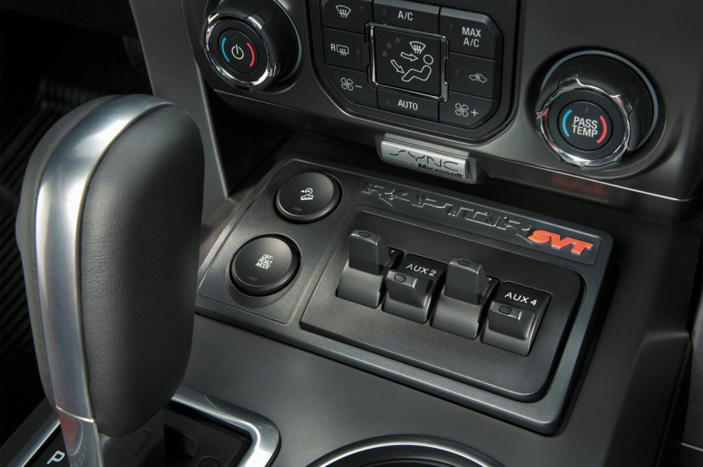
Step 1. Choose your upfitter switch based on the current draw your lighting device creates. To determine the amperage, divide the wattage of the device by volts (Amps = watts/volts). Some people divide by 12-volts, and some divide by 14-volts since your electrical system puts out over 12-volts when your engine is running and putting out a battery charge.
From the factory the switches are fused as follows (Fuse # in under hood fuse/relay panel):
AUX 1 30A (#18)
AUX 2 30A (#19)
AUX 3 15A (#44)
AUX 4 10A (#28)
WARNING – About Fuses & Wire Gauge (Size):
All the wires that “pass through” the firewall from the glove box area to under the hood are the same gauge. The actual AUX wires behind the glove box are sized according to what is appropriate based on their fuse rating.
Do not add larger fuses to the AUX 3 and AUX 4 switch. The wires running from these are not the same gauge as the wires coming from AUX 1 and AUX 2. Increasing the fuse size could allow to much voltage to pass through the wires and melt them potentially causing a fire. Yes I know, it’s dumb that Ford didn’t make them all 30A.
Note About Wire Connectors:
People have cut and beat up their hands trying to either get to the wires, or from trying to strip the coating from the wire and crimp on connectors.
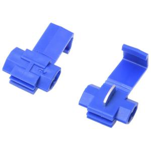
Some have find it easier to use a wire splice so you’re just squeezing the connector on the wires with a pair of pliers.
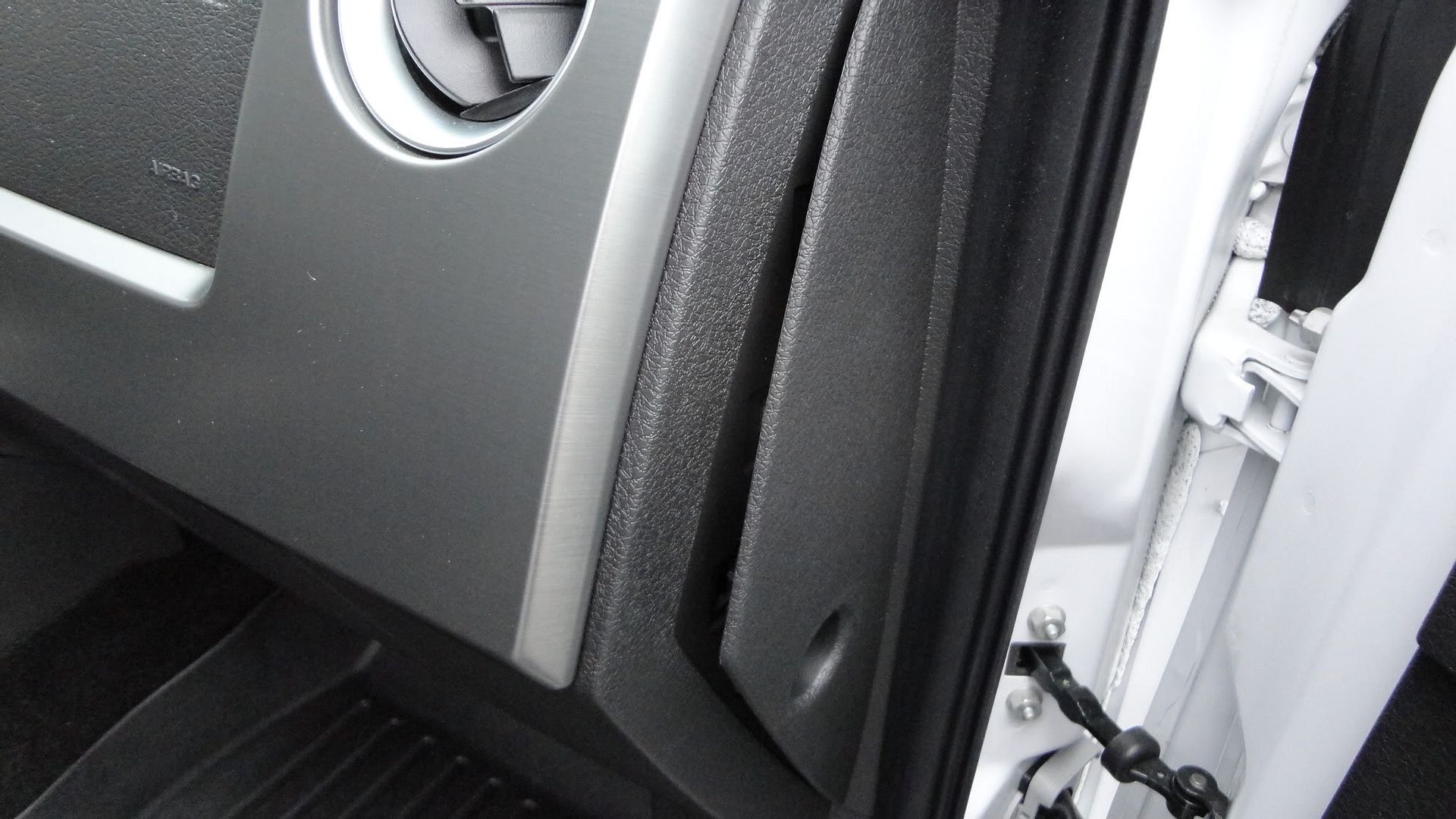
Step 2. Remove the dash panel on the passenger side by pulling straight out. It’s made easy by grabbing on to the vent hole and giving a gentle pull. Remove the panel and put aside.
Step 3. Release the glove box by opening it and pulling in the box sides to clear the rubber stops. The glove box will just hang down.
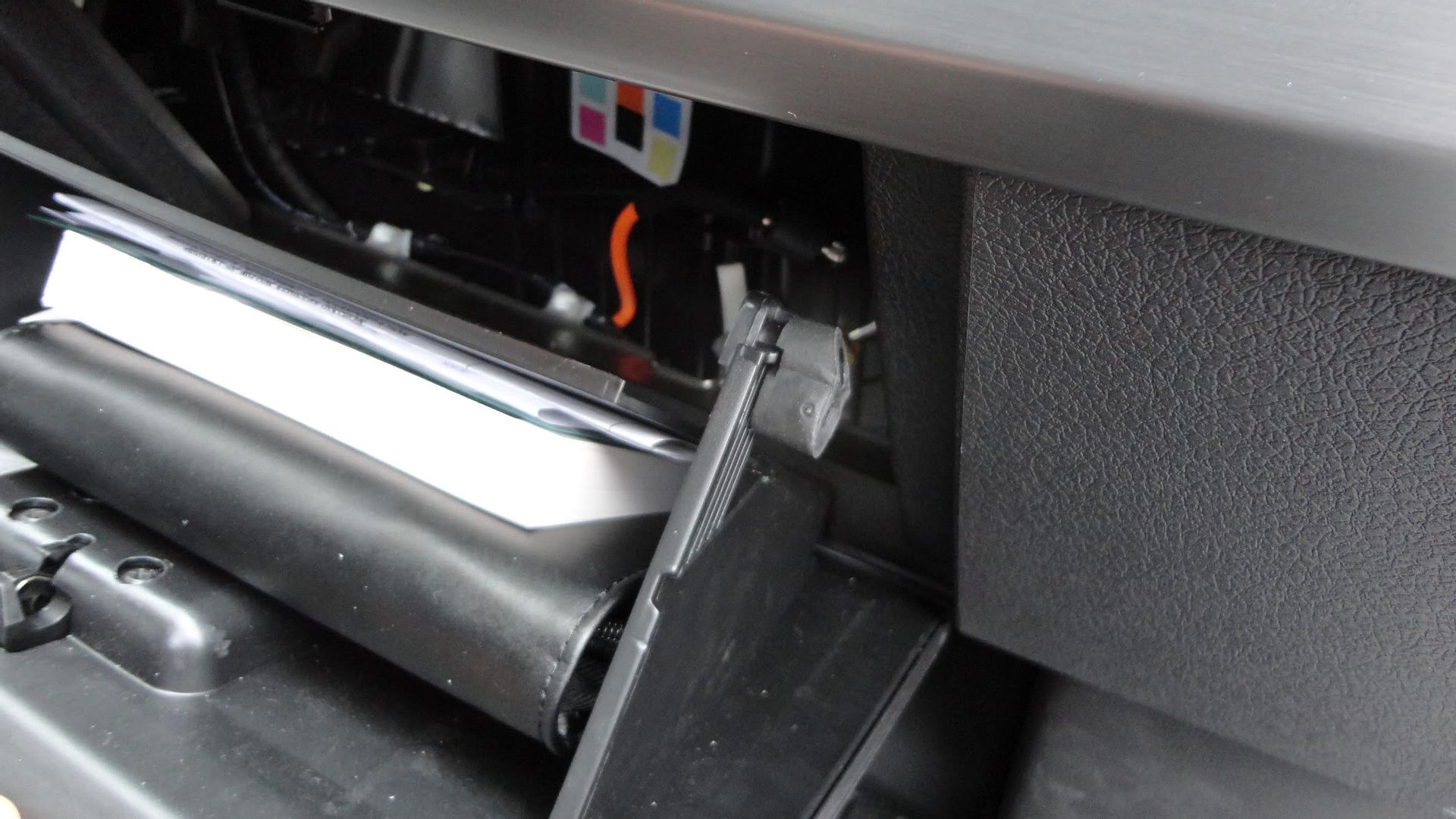
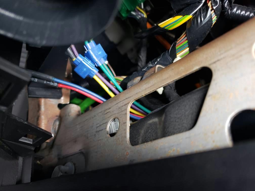
Step 4. Take a look inside toward the right the glove box opening. You will see (8) dead end wires. Based on which AUX switch you have chosen to use, locate the corresponding wire and strip it (make sure the switch is off of course). The +12v power comes from these wires.
AUX 1 Yellow
AUX 2 Green with Brown tracer
AUX 3 Purple with Green tracer
AUX 4 Brown
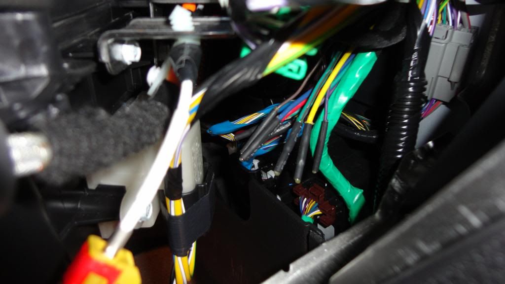
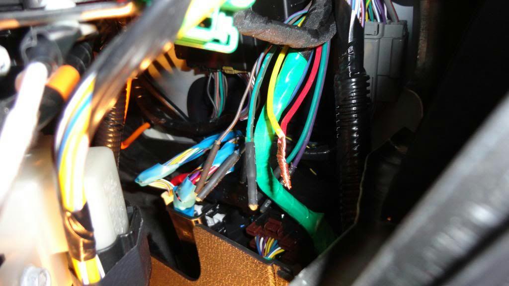
Step 5. The other (4) wires you will see – Green, Blue, Purple and Red are the “pass through wires”. One end of them is behind the glove box, the other end is under the hood near the firewall on the passenger side. These wires are “passed through” the firewall for your convenience. They do not directly correspond with any switches, they are just there to use. You simply pick one of the wires, connect your corresponding AUX switch wire to it with a crimp connector (or solder, but this can be difficult based on the limited space), and move to under the hood.
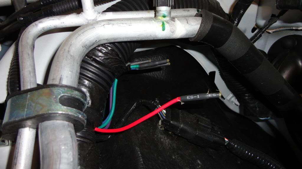
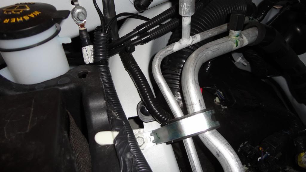
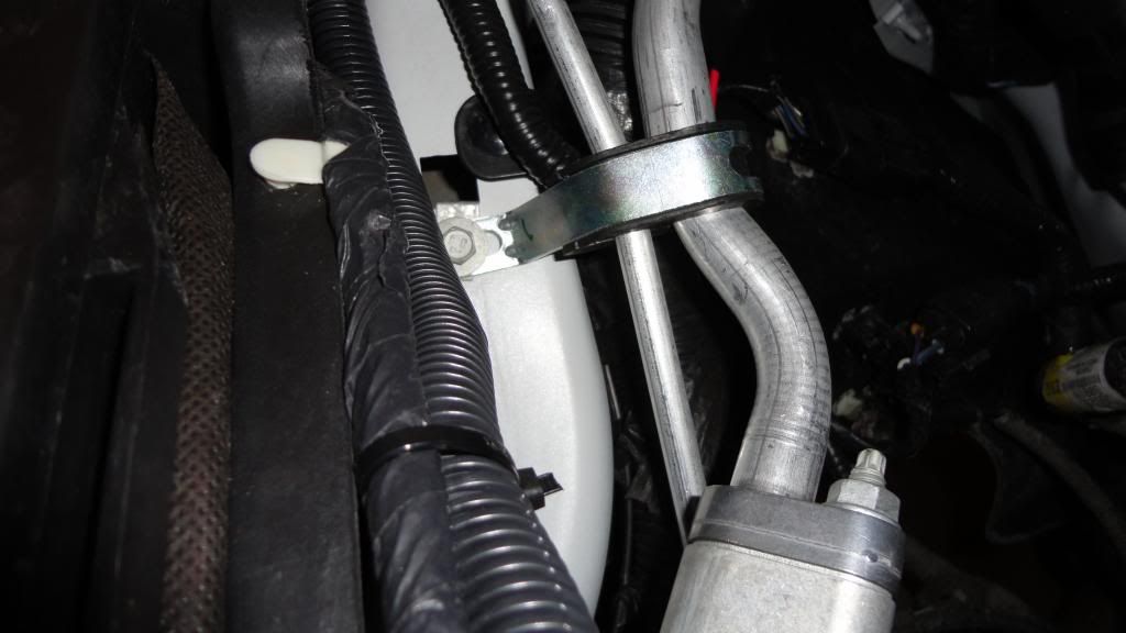
Step 6. Under the hood you will see the other ends of those (4) pass through wires – Green, Blue, Purple and Red. Whichever wire you connected your AUX switch wire to is the one that is now energized +12v (when the switch is on) and the wire you should use to run to your device.
From the factory, the pass through wires are taped to a wiring harness. Pull out the one you picked and proceed with your wiring.
Example: If you want to use AUX 1 to power your 40″ LED light bar, you will need to use the Yellow power wire that corresponds to AUX 1. You can connect the Yellow wire to any of the Green, Blue, Purple or Red pass through wires behind the glove box. So if you use the Red pass through wire, you will need to hook the positive wire from your light bar to the Red pass through wire under the hood.
Step 7. Once you have run more primary wire from the pass through wire under the hood to your light, you can move on to grounding the light. You can choose any of the factory grounding points that are very conveniently located near the pass through wires. I recommend just using a ring terminal and bolting under the factory ground point.
Step 8. With your wiring complete, using some flex conduit and zip ties will clean up your work. Proceed with all connections and securing wiring using good automotive wiring practices to avoid any future issues.
Resource: