Models Affected: 2017 to present model year F-250/350/450/550 Super Duty Trucks with optional Upfitter Switches.
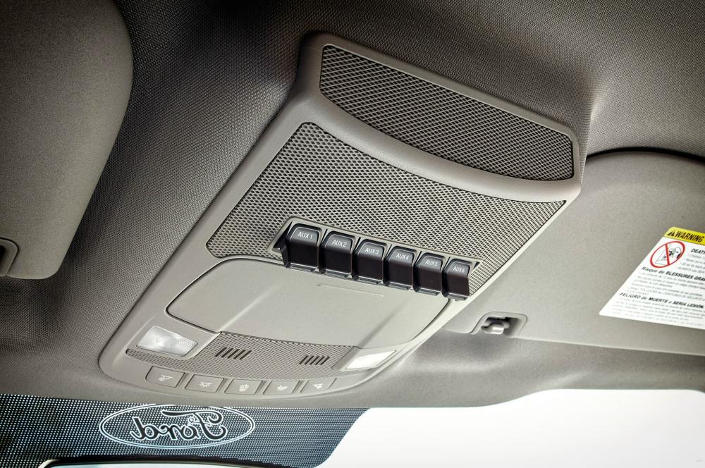
Description: The Ford Upfitter Switches are optional overhead console mount switches (Option Code 66S) that control under hood mounted relays. These relays power six blunt cut wires that are taped on a harness near the upfitter auxiliary relay box that can be found on the driver’s side of the engine compartment. The six blunt cut wires are as follows:
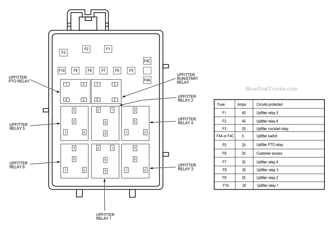
| Switches | Circuit | Color | Fuse # | Rating |
| Aux 1 | CB117 | Brown / Green | F10 | 25A |
| Aux 2 | CB114 | Violet / Orange | F9 | 25A |
| Aux 3 | CB116 | Blue / Green | F8 | 25A |
| Aux 4 | CB113 | Gray / Brown | F7 | 25A |
| Aux 5 | CB115 | Brown / Blue | F1 | 40A |
| Aux 6 | CB118 | Gray / Orange | F2 | 40A |
In addition to the upfitter switch blunt cut wires, this bundle contains the following blunt cut circuits:
| Description | Circuit | Color | Fuse # | Rating |
| Run/ Start Output | CB111 | Brown | F3 | 20A |
| Battery Hot Output | SB106 | Brown / Red | F6 | 20A |
| PTO Relay Control | CE924 | Blue / Green | N/A | N/A |
| PTO Relay Output | CB112 | Green / White | F5 | 25A |
All relays and fuses are located in the upfitter relay box.
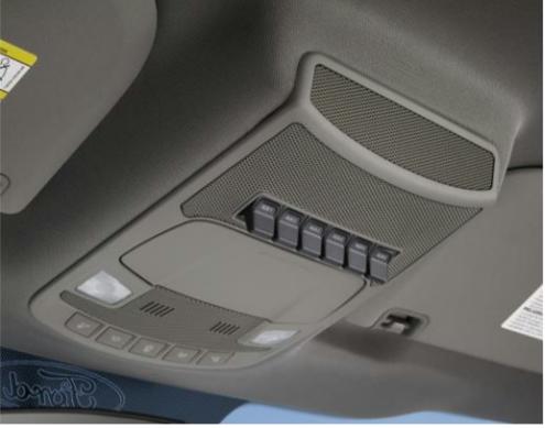
Figure 1: 2017 Super Duty Upfitter switch location
NOTE: Upfitter Switches cannot be added to a vehicle that was not built with this option at production.
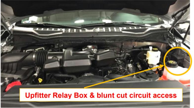
Figure 2: Upfitter Relay Box and upfitter switch blunt cut output location.
Accessing blunt cuts wires:
On vehicles with dual batteries, removing the upfitter relay box will provide additional access to the blunt cut wires.
1. Disconnect the electrical connector.
2. Release tabs and lift upwards to remove.
To reinstall upfitter relay box:
1. To install, reverse the removal procedure.
Configuring Upfitter Switches 5 and 6 to Hot-at-all times.
Upfitter relay box fuse F4 (5A) can be put into one of two positions. In Position A, auxiliary switch 5 and 6, operate with the ignition in RUN or START. In Position C, auxiliary switch 5 and 6 operate hot at all times.
The following procedure describes how to configure #5 and #6 upfitter switches to Battery hot.
1. Remove upfitter relay box cover.
2. Remove 5 Amp fuse located on the lower right hand corner of the upfitter relay box.
3. Slide the contact guard from position A (left) to position C (right) position.
4. Re-insert 5 Amp fuse into position C (right) position.
5. Replace relay box cover.
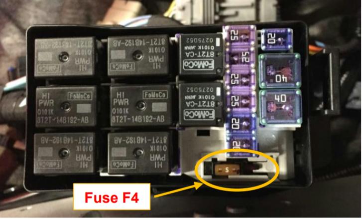
Figure 3: Fuse F4 location
Wiring Schematics
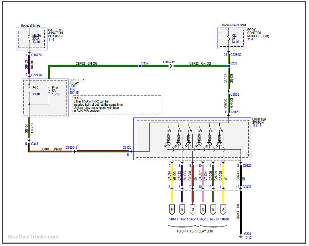
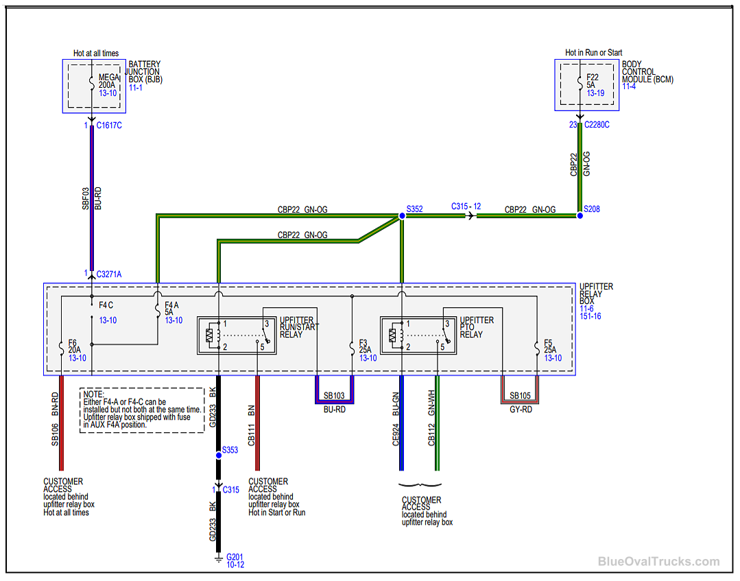
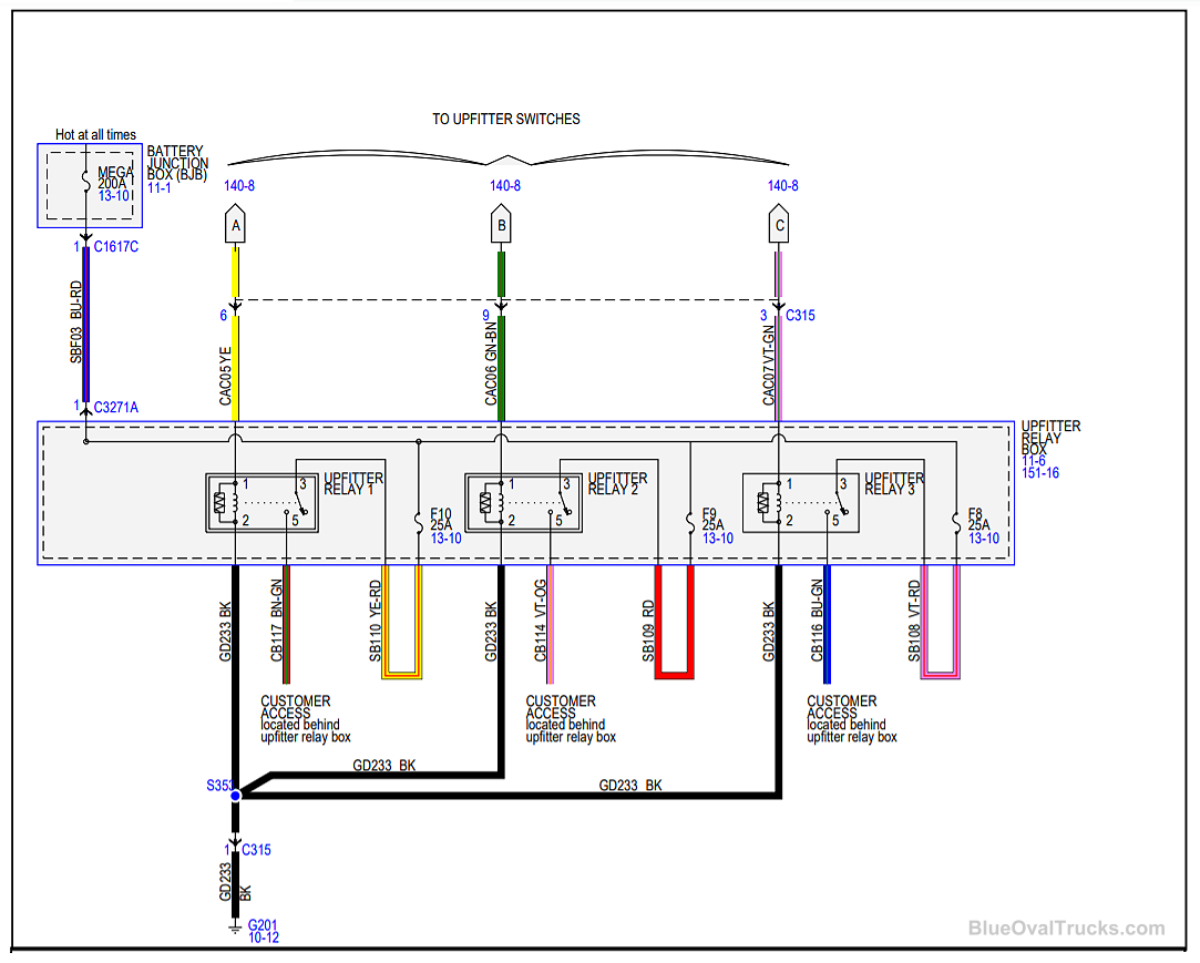
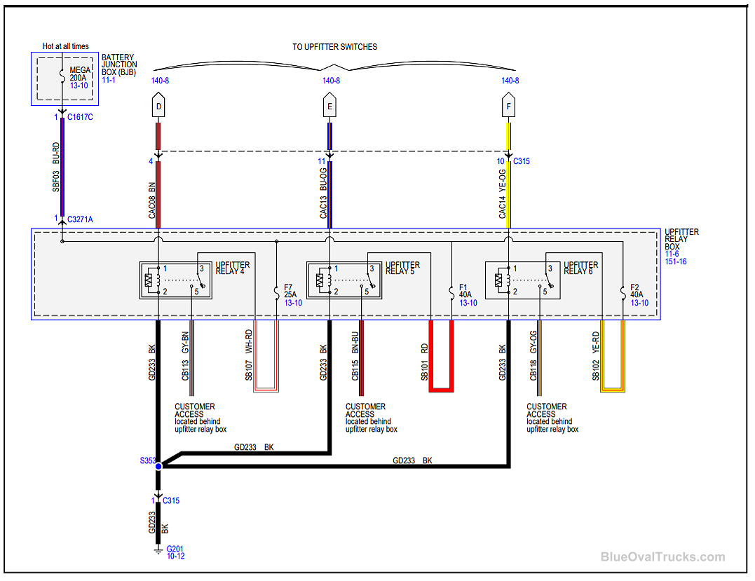
Relay & Fuse Diagram