
By: Jim Oaks
When I bought my 2010 F-150, one of the first things I needed to do was to add a controller for towing.
The truck already had the towing package, so all I needed was the brake controller and a hitch to go in to the factory installed receiver.
I chose a Hopkins Agility brake controller that I picked up from Tractor Supply.
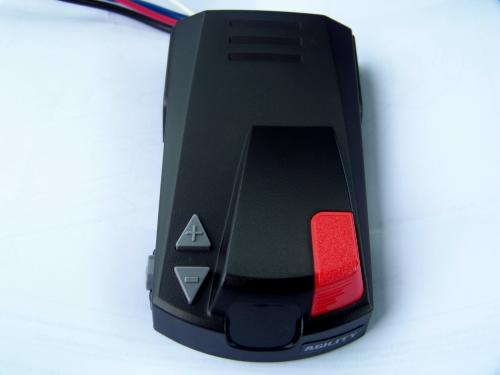
(Hopkins Agility Brake Controller)
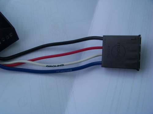
(Wiring on Hopkins Brake Controller)
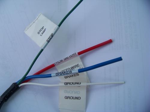
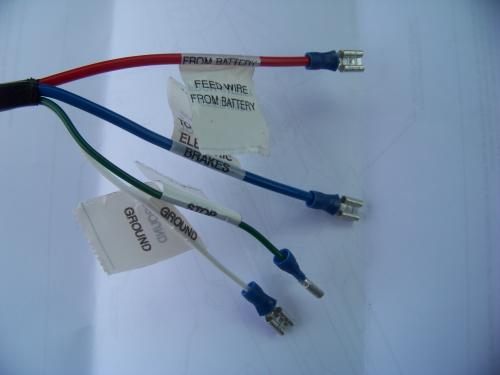
As you can see in the photo above, the Hopkins brake controller comes with all the wires labeled for easy identification.
The F-150 comes with a harness to easily add a brake controller. One end wires up to your new brake controller, the other end plugs right in under the dash. Hooking the brake controller up is as easy as connecting the wires from the brake controller to the harness and plugging it in.

(Ford Brake Controller Harness Provided By Ford (Above and Below))
(Factory Ford Brake Controller Harness)
The brake controller harness that comes with the F-150 is equally easy to use and well labeled.
I decided to add some female connectors to the end of the Ford harness so I could simply plug it in to the brake controller plug. Hopkins offers a harness that simply plugs in to the controller and truck, but it seemed senseless to buy a harness when Ford included one.
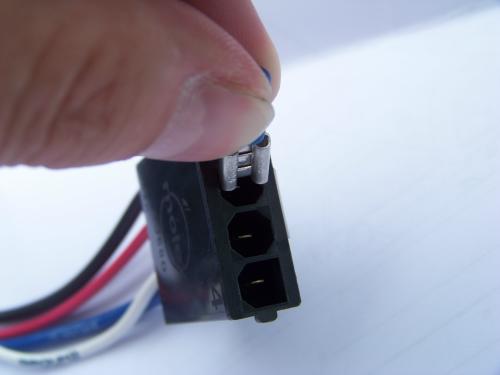
As you can see, the connector is a little to wide to fit in the connector. No problem.
First I crimped the female connectors to the end of the Ford brake controller harness.
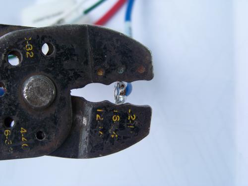
Then I squeezed the connector a little with my crimpers so it wouldn’t be as wide.
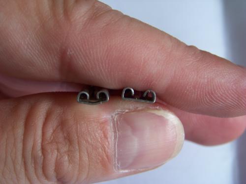
Above you can see how the one on the left isn’t as wide as the one on the right.
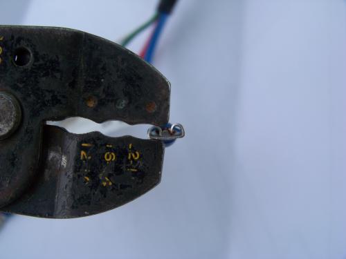
Then I squeezed them with the crimpers to close them back up some so they’ll stay connected to the connector and won’t slide off the male spade in the connector. Not the gap between the left side and right side.
Now the important part! NEVER assume the wires will simply match up by color. Follow the directions and labels on the wires. In the photo below you’ll see that some of the colors don’t match up.
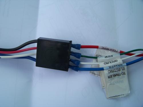
The Hopkins harness is as follows:
-
Black = Positive Terminal (+) On Battery
-
Red = Brake Switch
-
White = Ground
-
Blue = Trailer Brakes
The Ford harness is as follows:
-
Red = Fused Battery Feed
-
Green = Brake Switch
-
White = Ground
-
Blue = Trailer Brakes
Now that the harness is done, I needed a place to mount it.
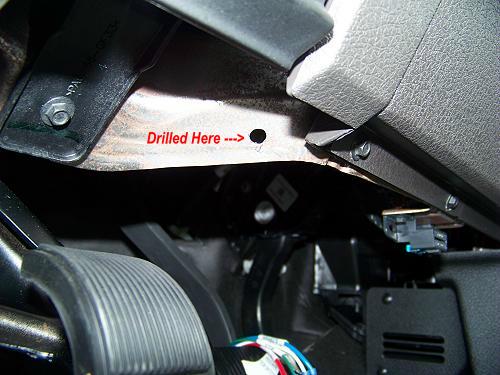
As you can see, there isn’t a flat spot under the dash to mount a bracket to. I really didn’t want to drill in to the plastic dash panel. In the photo above you can see where I drilled a hole in the metal under the dash.
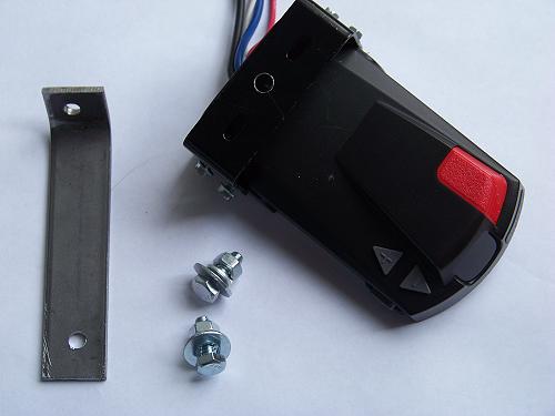
Above you can see the brake controller with it’s mounting bracket. You can see the hole I drilled in to it to bolt to the new bracket I made on the left out of 1/8″ steel.
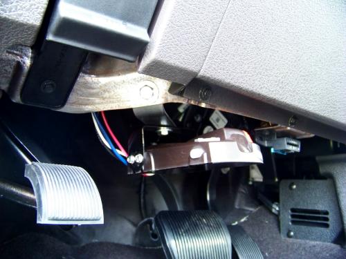
It’s not that clear in the photo above, But I used a piece of flat stock that I bent and bolted to the hole I drilled. The brake controllers bracket is bolted to the other end.
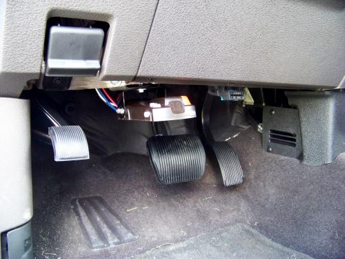
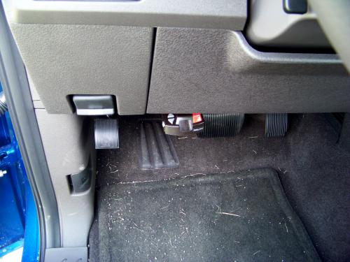
If I had tried to mount it to the bottom lip of the dash, it would have stuck out to far. Above you can see that you can see the controller, but it’s not in the way.
Now to connect it.
Look under the dash for the connection:
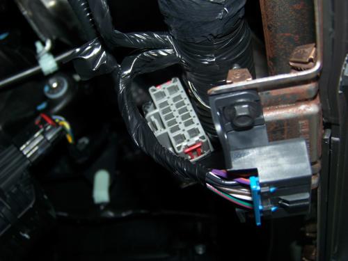
We want the plug that’s taped to the harness.
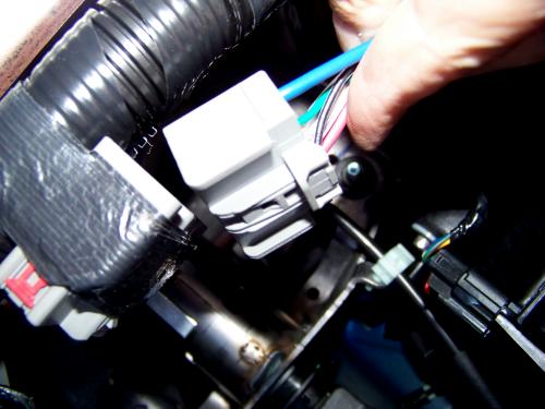
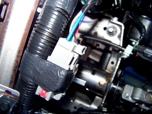
Unplug the harness (above).
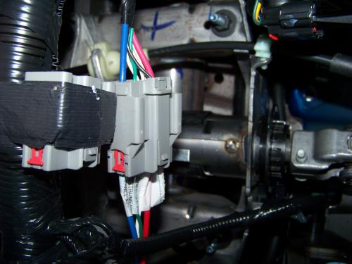
Plug your new harness in to that (above).
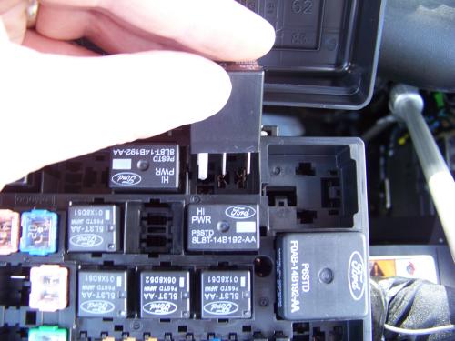
We’re not done yet. We need to add the fuse and relay for the brake controller in the fuse box under the hood.
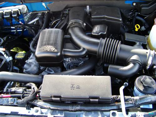
The fuse box is right in the front of the engine compartment.
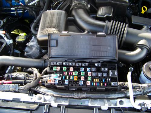
You need to install the fuse included with your Ford brake controller harness in slot #21.

Then install the new relay in slot # 9.

You’re done. Now just follow the directions from the brake controller manufacturer for testing the controller.