
Article By: 6.9 Turbo Install By Mel Agne
Preface:
In July of 1983, I took delivery of my Ford F-250, which I had ordered from Stoner-Wade Ford in Quarryville Pennsylvania two months prior. I was 20 years old at the time. The year 1983, marked the first year that Ford ventured into the Diesel powered pickup truck market, which up to that time had been the province of General Motors somewhat successful 6.2L Diesel. The 6.2 liters’ success probably would have been better, had the consumer base not been tainted by GM’s disastrous prior offering, the converted 350cid gas engine which was offered in numerous Chevy and Cadillac full size cars. Ford, sensing that the light truck market might be prime for a Diesel pickup based on a successful and proven engine design, turned to International Harvester to adopt their 6.9L (420cid) to pickups over 8500lbs, GVRW. The 6.9 was already in use by International in numerous trucks and buses of their own construction. Ford’s sales of the F-250 and F-350 Diesel pickups were slow initially, but grew exponentially through the 80’s as the IH Diesel won the trust of the buying public.
My 1983 F-250 has only 96,000 miles on it at this time, mostly due to my babying it for all these years. Not wanting to afford a new one, I have done my best to keep this one as good as new. I have however, paid the price of buying early. I have endured the advancements in injection pump, seal, and head gasket technologies, and have had to do more repairs to an engine with this low number of miles on it, than I would have expected. However, a Philadelphia Ford warranty adjustment agent told my dealer who was trying to settle a claim for me that “if he wasn’t going to drive it any more than that, he shouldn’t have bought a Diesel”. Maybe she was right. That, and my wife always said it would “rot” just sitting there.
This truck is currently on its third injection pump, and I had replaced the passenger side head gasket due to water leakage in the late 80’s. Throughout the 90’s, the Moose Truck (as it is so named), has been trouble free. Except for an alternator, water pump, and some batteries, I haven’t really done anything to it. This spring however, it became apparent that two problems were on the horizon. One was the right head gasket, which was beginning to leak oil at the rear, and two that the newer Power Stroke’s were pushing me out of the way on the interstates with their huge campers in tow. I had carefully observed the aftermarket turbo market for some time, and sat on the fence constantly as to the virtues of turbo charging. Thanks to Ford-Diesel.com and the members there, I finally decided to turbo. After evaluating the features and price of the three primary turbo kit providers, I decided on the Hypermax unit. The main deciding factor for me was the symmetry of the installation and the clean square mounting of the turbo. I also liked the idea of not having a Y pipe anymore. Regardless of the turbo considerations, I knew that the head gaskets were going to need to be replaced as a preventative measure if nothing else.
The following photo’s and text will be my attempt to explain how I did it, and how you the reader might try to proceed should you be interested in doing this kind of repair and upgrade yourself. If you’re only reading this for the head gasket or turbo portions, be sure to make the necessary adjustments to my instructions when re-assembling the engine. I take no responsibility however, for the accuracy of this information, or the consequences of any attempt to follow in my footsteps. Make no effort to criticize my methods. This is the way I did it, and I am in no way suggesting this is the only way. If you prefer to do it differently, feel free. Also note, that this is not a step-by-step explanation. This document should be considered a companion to any manual or plans you would use singularly. You should be warned that I am not a professional mechanic, and that I do not in any way consider myself an “expert”. I am a shade tree mechanic that just happens to have a comfortable garage. This project was done over the course of two weeks, and was not rushed. I’d like to thank all the individuals from Ford-Diesel.com who contributed information before and during the project.
I will offer only as much detail as is needed to generalize the procedures, except for areas that this project concentrates on specifically, namely the gasket replacement itself, and the turbo install. Read this entire document several times before starting. I HIGHLY recommend that you purchase TWO different service manuals, and follow the best procedure from either. I found large discrepancies between my 1983 Ford Service manual, and my 1999 Haynes Diesel Repair book.
The Tear Down:

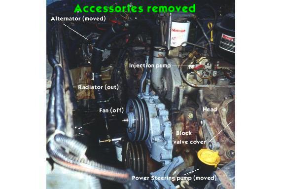
Accessories:
I always hate turning that first bolt. It can be hard to take a perfectly good running engine and begin to do things to it that give you nightmares, and wake you up in a cold sweat. It is an act of faith in oneself that it is a bridge you can cross and not look back. I don’t recommend it to the faint of heart. I also don’t recommend it if you don’t like wallowing in antifreeze, grease, Diesel fuel, or if you have a dislike for lower back pain, cuts and bruises and the occasional muscle cramp. It is also probably easier if you have a helper. I must have crawled out of the engine compartment 250 times. Begin by removing the batteries and draining the antifreeze. It would help if you put a rubber hose on the end of the petcock valve. I thought I’d be a smarty and just catch it in a pan. Too bad it hit the tie rod and sprayed all over the place. After your bath, remove the Radiator Shroud, Fan and Radiator, including upper and lower hoses. Getting the Fan off is easy if you have the special tool that you need. I then removed the Alternator, Power Steering Pump, and brackets. Remove the fuel output line from the fuel pump, the line to the injection pump and fuel return, and remove the Fuel Filter Mount. You will find removing the radiator allows for standing on the frame and steering box which contributes greatly to overall comfort during the project.
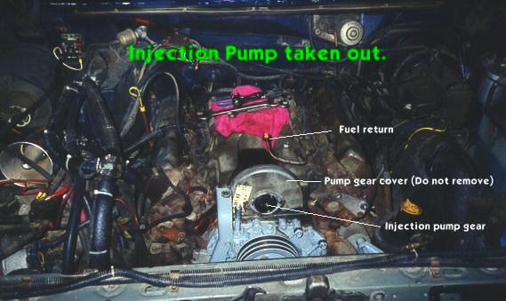
Injection Pump:
Note: You have now reached a point where rotation of the engine crankshaft is no longer allowed. Ensure that you have done everything to make sure that nothing turns the crank from this point onward! Disconnect all of the glow plugs from the glow plug harness. The connectors have a tab which must be squeezed to remove them. Then remove the injection pump. This is done by removing the Air Cleaner and Throttle Cable Bracket, then loosening all 8 injector lines from their respective nozzles. Disconnect the Fuel Return line from the top of the pump, and the Fuel Delivery Line from the Fuel Filter Mount. Then, using a Crows Foot wrench, loosen and remove the 90 degree fuel inlet adapter from the end of the pump. Remove the Oil Filler neck, and remove the 3 5/16” bolts that hold the injector gear to the pump. Remove the 3 bolts holding the pump to the pump gear housing, and pull the pump toward the air intake. Be sure to scribe a line between the pump and the housing so you can keep your timing adjusted!

Intake Manifold:
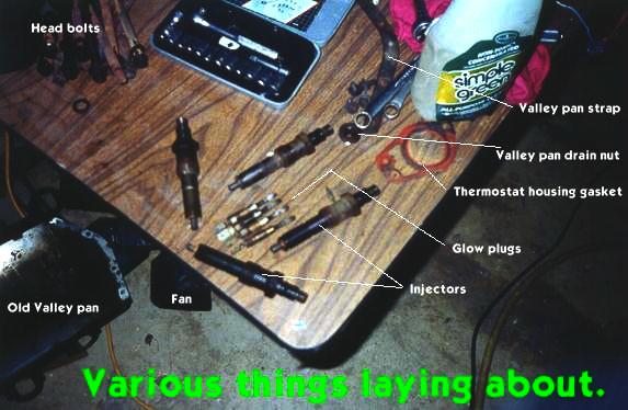
Remove the intake manifold by slowly loosening the attaching bolts a little at a time until all are loose. Note that this part requires a torque sequence to apply, so it makes sense to un-torque it accordingly. Once all the bolts are removed (two are shorter than the others and are at opposite corners), gently pop the manifold off the engine. The CDR valve will need to be pulled out of the Valley Pan grommet on the way off. If you’re lucky, you might find some tools that have been lost for a while laying under your manifold. I recovered a 1/4″ to 1/2″ socket adapter and a small wrench. No telling how long they had been there!
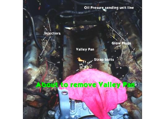
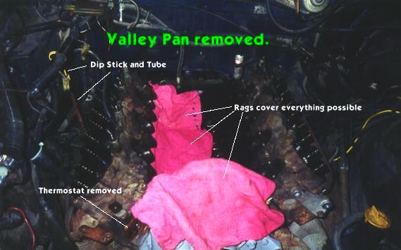
Valley Pan:
The Valley Pan is secured in the front by a steel V shaped piece of plate steel. The rear is held down with a unique looking nut, which takes a 1/2″ drive socket extension to unscrew. Water that falls on the engine is drained from the Valley Pan through this nut. The front and rear edges of the Valley Pan are sealed to the block with Silicone. My replacement pan came with special sealant and very specific instructions on how to apply it. Be sure to use a new Valley Pan, and follow the instructions that come with it when you re-assemble. Note that in the photo below, that the front retaining strap and bolts have been removed and are lying on the pan.
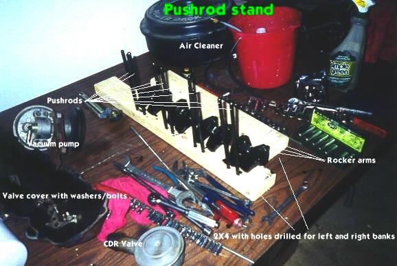
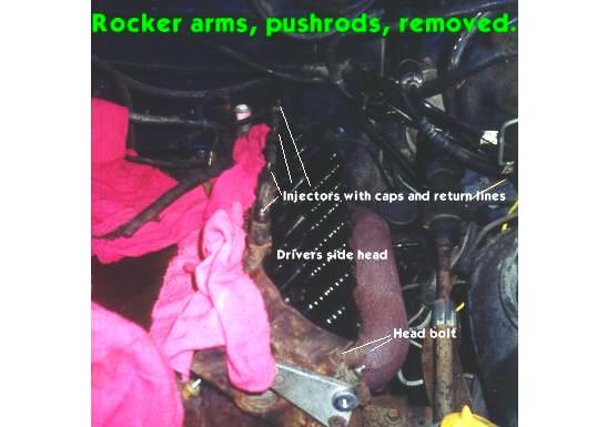
Head Prep:
The left and right Valve Covers come off next. Mine were originally held on with large Phillips type bolts. I replaced these with stainless hex head bolts some years ago. Remove whatever type you have, and wiggle the Valve Covers off. Next, build yourself something to keep your Push Rods and Rocker Arms organized in. I used a pair of 2X4s drilled to accept the bottom end of the Push Rods, and just placed the Rocker Arms next to them. It is important to keep the orientation and order of these parts exactly as they come out. You do not want to install a Push Rod upside down, or use them with the wrong cylinder, or Rocker Arms. Imagine each piece as being unique and treat them as such.
Note: The manuals seem to indicate that you should put the crankshaft in a particular position to install these things, so it would make sense to have it that way when you remove them. I didn’t do either, and suffered no ill effects. If you want to obey this instruction, then make sure you set the engine up that way earlier. You might be able to rotate it still, but I feel once the timing gear for the pump is no longer on the pump, that turning the crank is not what I want to do.
Remove the bolts holding the Rocker Arms down, and lift each pair off the head with its bracket and bolts as an assembly. Do not separate these items. Keep them clean for re-installation with their oily covering unchanged. The lubrication that they wear will help protect them when you re-start. Once all of the rockers and push rods are out, things get more serious.
At this point, your engine should be drained, stripped, and almost ready to take off the heads. There are only two things you should do first. One is, disconnect your exhaust pipe “Y” from the Exhaust Manifolds. It is not necessary to remove the exhaust manifolds from the heads at any time. The second thing, is to remove the dipstick tube. THIS MAY BE THE MOST DIFFICULT PART OF THE WHOLE JOB! I remember wrestling with the dipstick tube for 2 hours the first time I did the right head. The dipstick tube is press-fit into the block. I can offer no sure-proof way to remove it. I eventually got mine out by putting the tube through the hole in the handle of a crescent wrench, and prying against the exhaust manifold. You will need to plan on installing a new one.
A note about draining the block: Unless you remove the block drains, you will not be able to get all of the water out. I was afraid to mess with those things, so I used a shop-vac to suck as much coolant out of the thermostat housing as I could. This worked pretty well since when I removed the passenger side head, the small amount of coolant that did spring forth, did not go into the cylinders. I then used the shop-vac again to suck water out of the rear block coolant passages.
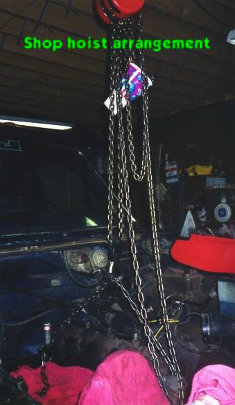
There are 18 head bolts per head. Loosen them slowly following the torque sequence in the manual. Remove all the bolts and washers that you can. Those in the rear that will not come out due to the firewall, or heater core housing will need to stay in the head until the head is removed. Make note as to which bolts these are, since you will need them to be in the head when you re-install. I would work on removing only one head at a time. After you have removed all the bolts, rig a hoist to lift the head from the engine. But first, a story.
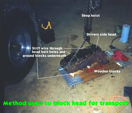
Once upon a time, I didn’t have a hoist, and I did this job alone with just my arms and back. I was a lot younger then. Getting it off, wasn’t anywhere near as hard as putting it back on. The first time I changed my passenger side head gasket, it still leaked when I was all done. I ended up taking it to the Ford dealer to let them re-do it. This was my fear that I might fail again this time. However, I took my time, had better tools, and knowledge to use, and am glad to say I was successful. Having done the job both ways, I would never try it again without a hoist. If you’re going to use a hoist, take the hood off your truck as step number one. If you’re going to use a cherry picker, or your muscles, you could omit this step.
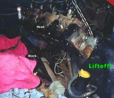
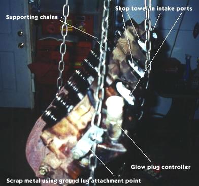
Rig the head for removal as shown in the picture. Remember that the head has two alignment dowels in the form of two metal sleeves that sit in some oil passages between the block and head. The heads cannot be lifted straight up. They must be lifted “out and up”. I accomplished this by lifting with the hoist, until the motor and truck started to move. I then beat on the head with a rubber mallet while pushing the hoist “away” from the block. The head then popped free. Note that the alignment dowels may stay with the head or block. You will want to capture them and set them aside.
In case you’re curious, the big plastic cup catches the free chain from the hoist as the head is lifted. Professionals have a fancy leather bag to do this.
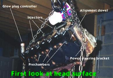
Note that the alignment dowel came out with the head. This will need to be pulled out, and re-inserted in the block just prior to re-assembly. I removed my Injectors and Glow Plugs after the head was removed. You could do it before hand if you prefer. After inspection, I recommend having the heads thoroughly checked. I took mine to my Ford dealer and had them check the valves. They found a cracked valve seat, which they replaced. I then had them send the heads out for cleaning, and Magnafluxing to check for cracks. They came back with a clean bill of health. The picture below shows how I fastened wooden blocks to the heads to keep them upright and safe from nicking or scratching. I also had my injectors tested, and one of them came back as being bad, so it was replaced with a new one. I didn’t reinstall the injectors until the Heads, Valley Pan and Intake Manifold were back in.
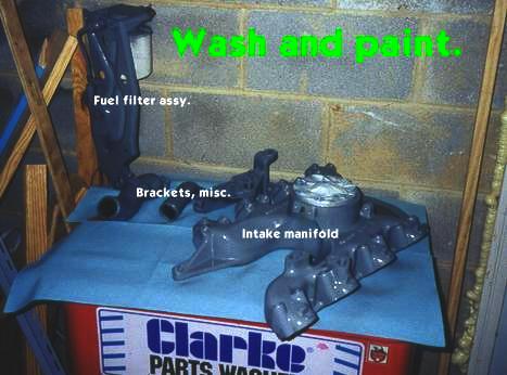
While you’re waiting for your heads to come back, you might want to throw everything you’ve taken out (except the Push Rods and Rockers) into the parts cleaner, and give everything a good coat of paint. I couldn’t find a good match for the original International colors, so I chose a nice machine gray. I didn’t use any fancy high temperature stuff, I just went with good old Rustoleum. It probably wouldn’t hurt to use the high temp stuff, but I used what I had. So far, its all still there, and doesn’t seem to be burning off. I also painted the heads when they came back, but did not paint the exhaust manifolds, which remained attached. When I painted the heads, I used the valve covers as a protective lid and put tape over the intake ports, and put paper towels in the injector holes. I used an old glow plug to cover the glow plug hole, the bad injector to cover the injector hole, and I just moved them from cylinder to cylinder as I painted that area. When I painted the fuel filter stand, I left the old filter on, knowing that I would be replacing it during re-assembly.
Putting It Back Together:
Surface Preparation and Head Gaskets:
The biggest difference between my Ford shop manual, and the Haynes manual, was the paragraphs devoted to the discussion of surface preparation prior to installation of the head gaskets. The difference was, the Haynes manual had one. The Ford shop manual didn’t! I attribute the lack of knowledge about surface preparation and the lack of the Haynes manual to my earlier head gasket replacement failure that I spoke of earlier. Perhaps because the Ford shop manual was intended for professionals, they assume that all mechanics know about such things, but alas I did not. So, for the benefit of all I’ll simply state that the block and head mating surfaces must be squeaky clean, and totally free of all old gasket material. I labored for several hours cleaning the block deck with Lacquer thinner and scraping off old gasket material with a single edged razor blade. I went so far as to insure that not even a fingerprint remained on either when it was time to put the gasket in. Which is a good segue to the topic of gaskets. I researched this a fair amount on the Ford-Diesel.com web site, and while Felpro gaskets seemed highly rated, I decided to get mine from the Ford parts counter. The Ford part is a nice box that says Ford on it, and once opened contains two virgin International service parts, still in their International service part shrink-wrap cardboard containers. Knowing this, I would have certainly saved a few dollars by going to IH, but since I get my Ford parts at a discount I suppose it didn’t make much difference. There have been a few changes to this head gasket design over the years. The pictures below tell the tale.
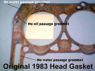
The original 1983 gasket did not have any rubber grommets of any kind. This led to early failures in the form of external water leaks thanks deformation of the passageways.
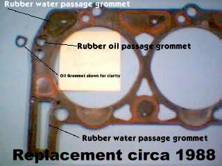
In response to the problems imposed by the original design, rubber grommets were introduced around 1988 in the water and oil passageways to correct the leaks. Almost.
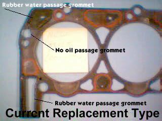
Over time, the rubber gasket on the oil passage broke down and got mushy. This allowed oil to leak externally, and probably degraded the gasket itself over time. So, the third and last revision reverts the oil passage to a non-rubber passageway, while retaining the useful and working rubber water passage grommets.
In addition to cleaning the surfaces, attention must be paid to the head bolt holes in the block. Since this is a Turbo Charger install project, the head bolts will be torqued on installation to the non-factory setting of 85 foot pounds, which is 10 pounds more than the manual recommends. Two things to keep in mind on this. First, is that the threads on both the bolt and the hole need to be clean with no rust or debris. I chased the threads in the block with a tap several times to clean them out. I oiled the tap each time to make the dirt stick to the tap. Since I was using new head bolts, I didn’t worry about them too much. I visually inspected each one and they appeared to be good to go. Secondly, since I’m to over-torque these, I wanted to make sure my torque wrench was accurate. I sent it to Team Torque (www.teamtorque.com) to have it calibrated. Good thing I did, because my wrench was actually about 15 pounds higher than what the setting on it said. I doubt very much if my head bolts would have made it to 100 pounds. They are a tad wimpy, being only 7/16” in diameter, and you will find that pressing them to 85 pounds will make you feel that they will snap at any minute. But I digress. Do the taping before you do the cleaning so there is no oil left on the block deck. Also re-insert the alignment dowels in the block as a final step prior to re-installing the heads. Use a shop vac to suck out any debris from the cylinders, passageways, and bolt holes. Once your sure everything is clean and worthy, put the head gasket on the deck over the alignment dowels. Press the steel-cored water passage grommets into the gasket, and lower the head on gently, trying to match the angle of the dangle with the block. Make sure you remember to put the head bolts and washers in the holes that you couldn’t get out of the head when it was in the truck. Otherwise, you won’t be able to put them in the head when it is on. Use rubber bands to hold these difficult bolts in such a way, that the end of the bolt is flush with the bottom of the head when you install the head on the gasket. After the head seats on the alignment dowels, you can remove the rubber bands, and let the bolts drop into the block holes. I decided to use new head bolts in this job, but there is some debate as to the necessity of this. Frankly, even though the bolts are a tad expensive, I think putting new ones in is worth it, since some of the old ones are exposed to the elements in their length due to the way they pas into the block on a chamfered edge near the exhaust manifold. After 17 years, the ones on the drivers side had actually started to rust through. While I did purchase new bolts, I failed to purchase new washers. This ended up causing me grief, as one of the washers gave out while being torqued, and ruined my torque sequence. With help from others on the Ford-Diesel web site, I determined that I could safely replace this single bolt after all the others had been torqued down. Since it was Sunday at the time, I had no way to buy a new one. Monday morning, I got one at the International dealer and installed it without difficulty. The bolt in question was the one on the end near the front, accessible from outside the valve cover on the passenger side. Torque the heads to spec using the Hypermax manual, or the picture in your service manual. Be sure to do it at four different levels about 20 pounds apart. The bolts and washers should be lightly oiled. DO NOT USE NEVER SEAZE on the bolts!
Reassembly notes:
Proceed to put the engine back together in reverse procedure, with a few exceptions. Do not re-plumb the injector fuel returns without consulting the Hypermax manual. I replaced all my T’s, O-Rings and hoses with new. Refer to the Hypermax manual, and use a Greenlee punch to make the 1-5/16” hole in the left valve cover. Leave both covers off until you read my notes on the valve covers in the Turbo Time section. Install your Push Rods and Rockers before you put the Valley Pan on so you can watch the Push Rod ends seat in their Hydraulic Lifters. Also, before installing the new Valley pan, examine the area below the CDR valve drain hole. The Hypermax installation instructions tell you to perforate the pan to allow for better drainage from the turbo lube oil return. I examined mine, and decided that the manufacture had allowed plenty of drainage already, so I omitted this step with no ill consequences. Apparently only some valley pans will require this step due to a “manufacturing variance” to quote the manual. Go ahead and put the rubber plug that Hypermax provides in the back of the intake manifold before you put it on the engine. Be sure to follow all instructions in your service manual during re-assembly, including the torque procedure for the Intake Manifold. At this point, we will proceed directly to the Turbo portion of the project, so the engine accessories and radiator will remain out for ease of access. If I were to do it over again, I would turn up my pump BEFORE I put it back in the truck, so you may want to do that. Again, refer to the Hypermax documentation for instructions on that procedure.
Turbo Time!
The Hypermax manual is really the best thing to guide you at this point, but the purpose of this article is to point out some of the pitfalls, and recommend what I think would be the best way to do it. So, following roughly along with the manual, here is the order I think it should be done.
Turbo Installation prep:
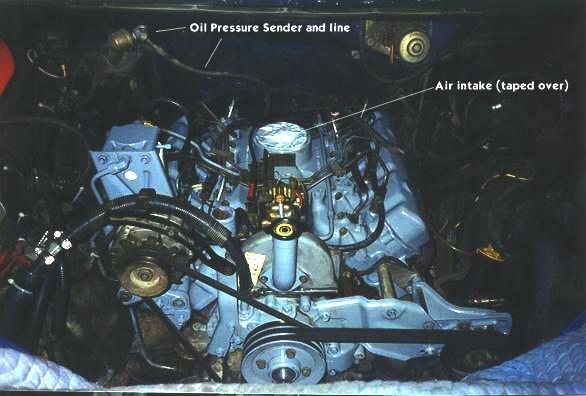
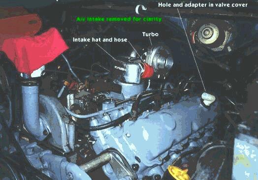
After verifying that you have all the parts necessary, begin by modifying the drivers side Valve Cover. It will take a few minutes to identify the parts they call the “Grommet and Baffle”. You’re looking for the shiny metal thing that is bent into the shape of two circles with flat edges connected together and facing each other. The big rubber donut is the Grommet. You can confirm you have the right pieces by fitting the Grommet into the Baffle ring, without worrying about the Valve Cover. After you’ve found these parts, install them in the Valve cover as per the Hypermax instructions. If you didn’t install the rubber plug in the old CDR valve hole behind the air intake on the Intake Manifold, you should do that now. If you have an older truck like mine that requires re-location of the Oil Sender unit, do that next.
Valve Cover Notes:
I recommend that you use a new gasket with the valve covers. Use Blue silicone sealer on the Valve Cover side of the gasket, and press the gasket into the valve cover, making sure that the sealer is contacting both surfaces all the way around. Let this material set up for a few minutes. While it is doing so, take a rag with some Lacquer thinner on it, and wipe down the gasket mating surface on the top of the heads. They should be clean and free of any old sealant or gasket material. Put the Valve Covers on then, and install the valve cover bolts and backing plates (those triangular things). Make sure you get the correct orientation on the backing plates. Their job is to spread the tension across the valve cover and they should be bowed slightly so that the center is higher than the ends. You may need to flip them over to achieve this direction, as after they are torqued they are lower in the center and will have been bent this way from previous use. There is no need for sealer on the gasket to block mating. As long as you don’t over-torque the valve covers (7 pounds according to my manual) they will not leak.
Getting On With It:
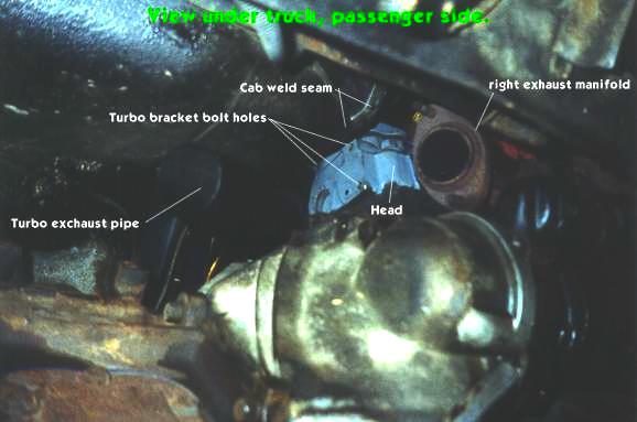
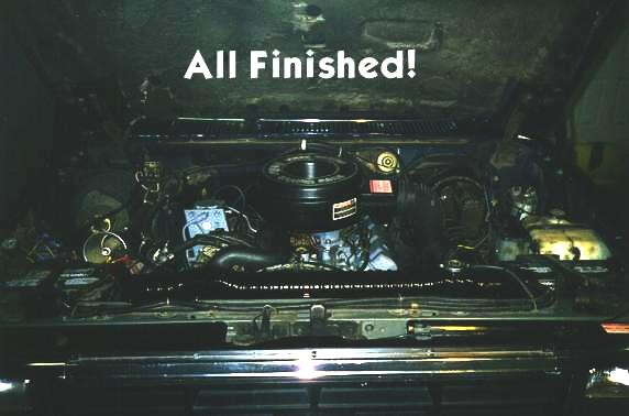
This was my engine at the beginning of the Turbo installation procedure. Nice how that fresh paint makes it look eh? I should have painted a few of the smaller parts. Oh well. This is still a real truck, and not one of those car-show only deals. There is really only two things that make the Hypermax turbo installation challenging. They are the Turbo exhaust (down pipe) pipe and the bending of the firewall flange. It seems any Turbo installation (ATS, Banks, or what have you) requires you to mess with the firewall flange (cab weld seam). What a pain. All I can say is do your best. I had a particularly difficult time with this, and it is my hope that you will make out better. Some have had success by sawing notches in the flange and then bending the pieces over as individual tabs. I think the tools you have at your disposal for prying may be a big factor. I knew what I needed to do it the easy way, but just didn’t seem to have anything shaped like what I needed. Crowbars, big screwdrivers, saw-zalls, all these things will be tried. The tuff part for me was getting the drivers side pipe to clear between the bell housing and firewall flange. I had tons of room near the bell housing, but none around the flange. I was tempted to bend the Hypermax pipe, but ended up not doing so. Another area that may need persuasion is the heat shield under the passenger side floor. I discovered the down pipe was rubbing after I had everything installed. I would recommend removing this shield or bending it all the way against the floor before you install the down pipe.
Speaking of the down pipe, the Hypermax manual tells you to install this after you install the Turbo Mounting Bracket. DO NOT DO THAT. Drop the down pipe into place as step number one! I ended up taking the bracket out to get the pipe in between the engine and firewall. This will be a little like one of those Chinese torture puzzles. You will have to get these two parts to fit in the same space, but I think if you put the Turbo Exhaust pipe in first, you will find it easier than doing it the way the instructions say. Mount the Turbo Bracket next, fastening it to the passenger side head with the 3 bolts they provide. Continue following the Hypermax directions. The next element of torture you might encounter is trying to tighten the bolts that hold the Turbo Charger onto the mounting bracket. There are 4 bolts, and the two on the left are easy. The two on the right (drivers side, we are looking from the front now) however, are another matter. The lower right one you can do with a 3/8” drive extension and universal joint socket. The upper right one however, I could only do one flat at a time with a short open-end wrench. A standard length wrench will be too long. Another difficult task is installing the short ¼” bolt into the exhaust pipe flange where it meets the Turbo Mount. The pipes running from the exhaust manifolds to the Turbo must be positioned just so, and the bolt hand-threaded into the mount through the flange. This isn’t so tuff, however, beware. If you have a manual transmission, there are vent holes for the clutch in the bell housing. There is the POTENTIAL to drop one of these little bolts into one of those vent holes. Can you say “Oh Darn? Boys and girls?” I’d recommend stuffing a rag in those vents to prevent such a problem. Don’t forget to pull them out later. After mounting the Turbo, and hooking up the exhaust pipes, it is a simple matter to install the Intake Hat, hoses and Air Cleaner mount. I discovered that the holes used by the Air Cleaner mount, are the holes IH uses to mount a fuel filter. It seems that the Fuel Filter mount used by Ford is not used by IH in their own applications. This is probably due to under the hood clearance differences between a Ford F series pickup, and an International S-1600 chassis. When you install the Air Cleaner mount, you may notice that it sits on, or rubs, some of the injector lines. I compensated for this by installing additional washers under the Air Cleaner mount until it cleared the lines. This also helped the air cleaner sit more level.
The earlier versions of the Intake Hat did not have a chamfered edge on them, and the rubber gasket, which goes over the air intake, and beneath the hat, would be cut easily during the hat installation. This was changed on later castings, making the Intake Hat installation easier. In either case, be sure to coat the rubber gasket with some oil, and ensure that the Hat seats on the gasket, and intake properly. I found the easiest way to install the Intake Hat, was to not worry about the orange colored hose while putting on the Hat. I installed the orange Boost Hose after the hat was tightened down, by removing the hose clamps, and pushing the Boost Hose on. I then undid the clamps all the way, and put them around the hose separately.
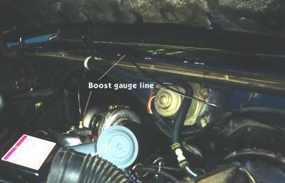
Hopefully you have purchased a Pyrometer and Boost (Manifold Pressure) Gauge to go along with your turbo installation. Hypermax provides a mounting port on the passenger side header pipe for your thermocouple probe. You will need to use the small pipe plug furnished with the kit to plug this port if your not installing a probe. The Intake Hat also has a threaded hole for your Boost Gauge tube. I would strongly recommend filling this hole with a Boost Gauge, and not the little pipe plug they supply. Not knowing how much boost you’re making, is a sure way to undo all the hard work that went into your engine. 12 pounds is max, and I would hesitate to stray too far over 10. These are high-compression engines, not really designed for Turbo Charging. Allow me to offer the following letter from International that I received while researching this project as a fair warning….
| Hello Mel,
We are happy to hear that your truck and engine are doing so well. Ford part number E7TZ 6051 BRM is a 6.9L head gasket kit and Ford part number E7TZ 6051 C is a single gasket. The gasket for the Ford application for your vintage is identical to the International application. An International dealer will have a head gasket as part number 1804259C6 (or C7). I must caution you that your 6.9 L engine block was not designed to support a turbocharger. It would be a shame to have your engine that has lived so long destroyed by a turbo. I don’t have specific information to share with you on this but I know we have seen engines in reman that have been damaged beyond repair as a result of turbocharging. We don’t have any sales information in our office on the older vehicles. I will ask my contacts at Ford if they have any access to this information. Good luck at the next truck show!! Liz Zid
|
Of course, Liz doesn’t get on Ford-Diesel.com very much.
Ironically, Rudolph Diesel never lived to see the success of his vision. He suffered from intense migraine headaches, so severe that it is believed he took his own life while crossing the English Channel on September 29, 1913. His body was never found. Let our hobby be a tribute to this man who gave us so much.
Source:
This article was written by Mel Agne and posted at www.ford-diesel.com (no longer exists). It has been preserved here to ensure that the info is always available to the Ford diesel truck enthusiast.
About The Author
Growing up, my father always believed that every family needed a truck—there’s just something about having a vehicle capable of hauling anything at a moment’s notice. That philosophy stuck with me, and it’s been the foundation of my lifelong passion for Ford trucks.
While I’m best known for my work with Ford Rangers, I’ve owned a wide variety of Ford trucks over the years—including F-150s, F-250s, F-350s, and even larger rigs like the Ford Excursion, Ford Expedition, and a 1982 Ford Econoline Sportsmobile camper van. I’ve used these vehicles for everything from family transportation to towing car trailers and campers, and each one has fueled my love for Ford’s versatility and durability.
I especially enjoy the styling of 1970s and 1980s Ford trucks—the bold designs, rugged presence, and classic charm are timeless. Sharing my passion for Ford trucks, vans, and SUVs with other enthusiasts online brings me a great deal of joy, and it’s why I created Blue Oval Trucks.
This website is dedicated to helping Ford truck enthusiasts explore, learn about, and celebrate these incredible vehicles. While I share my expertise and experiences here, Blue Oval Trucks is an independent enthusiast site and is not affiliated with Ford Motor Company.