
IINTRODUCTION
IMPORTANT DISCLAIMER: The provided tire/wheel fitments are approximate. Actual dimensions of a given tire size can vary considerably from one brand to another. Manufacturers’ wheel offset and backspacing measurement points are not always consistent. Backspacing greatly impacts tire-to-fender clearance when turning. Wheel width and backspacing influence whether the tires protrude past the fenders, and to what extent. Considering these important factors, we recommend that you fit-check your tire/wheel selection prior to purchasing.
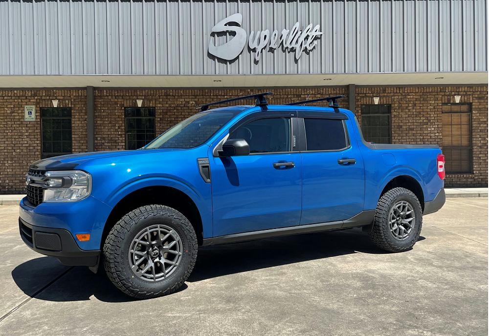
Upgrade your suspension with an American made Superlift 2.5″ lift kit. Superlift 2.5″ lift kits come as a complete replacement suspension lift. This kit includes all front and rear lift components and hardware required for a smooth ride. Most kits come with coil springs and shocks. Order your Superlift lift kit with Superlift shocks or upgrade to Bilstein 5100 series shocks.
Add larger wheels and tires and accomplish an aggressive stance with a Superlift 2.5″ lift kit. This kit comes with step by step instructions and vehicle specific hardware to ensure a precision fit. Superlift stands by their product and backs there lift kits with a limited lifetime warranty. Superlift lift kits. Take the road less traveled with a Superlift lift kit
PRODUCT USED
The page will show you how to install the Superlift 9755 2.5″ lift kit for the 2022+ Ford Maverick.
Check it out at:
Superlift Ford Maverick Lift Kit Instructions (PDF)
KIT BREAKDOWN
Quantity – Part Number – Description
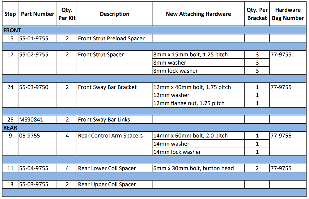
(4) PN# 05-9755 – Rear Control Arm Spacers
(2) PN# 55-01-9755 – Front Strut Preload Spacer
(2) PN# 55-02-9755 – Front Strut Spacer
(2) PN# 55-03-9750 – Front Sway Bar Bracket
(1) PN# 55-03-9755 – Rear Upper Coil Spacer
(2) PN# 55-04-9755 – Rear Lower Coil Spacer
(2) PN# MS90841 – Front Sway Bar Links
(1) PN# 77-9755 – Hardware Bag
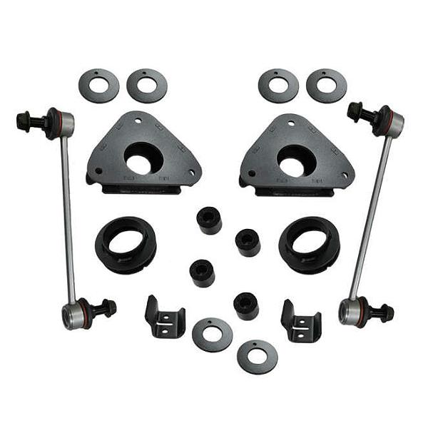
Superlift 9755 2.5-Inch Lift Kit
INSPECT ALL PARTS
Prior to beginning the installation, OPEN the Boxes and CHECK the Included Components Compared to the Parts Breakdown. Check all parts and hardware in the box with the parts list below. Be sure you have all needed parts and know where they install.
IF you find a packaging error, contact SUPERLIFT directly. Do not contact the dealer where the system was originally purchased. You will need the control number from each box when calling; this number is located at the bottom of the part number label and to the right of the bar code. •
PARTS LIST
The part number is stamped into each part or printed on an adhesive label. Identify each part and place the appropriate mounting hardware with it.
Installation requires a professional mechanic. The overall vehicle must be in excellent working condition; repair or replace all worn parts.
Read instructions several times before starting. Be sure you have all needed parts and know where they install. Read each step completely as you go.
NOTES:
• Front end alignment is necessary.
• Do not fabricate any components to gain additional suspension height.
• Prior to attaching components, be sure all mating surfaces are free of grit, grease, excessive undercoating, etc.
• A factory service manual should be on hand for reference.
FRONT INSTALLATION
Save all factory components and hardware for reuse, unless noted.
1. Disconnect the battery.
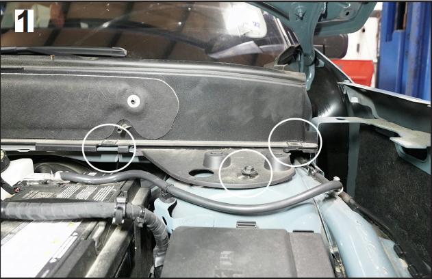
2. [Illustration 1] Under the hood, remove clip holding the windshield wiper cover.
3. [Illustration 1] Lift the windshield wiper cover, then unbolt and remove the strut cover.
4. [Illustration 2] Unbolt the upper strut bolts. [13mm]
![Unbolt the upper strut bolts. [13mm]](https://www.blueovaltrucks.com/wp-content/uploads/2026/01/superlift_ford_maverick_lift_kit_600.jpg)
5. Secure the vehicle on jack stands with a jack under the lower control arm.
6. Remove front tires.
7. [Illustration 3] Disconnect the tie rod from the knuckle. [15mm]
![Disconnect the tie rod from the knuckle. [15mm]](https://www.blueovaltrucks.com/wp-content/uploads/2026/01/superlift_ford_maverick_lift_kit_700.jpg)
8. [Illustration 4] Remove and discard the sway bar link. [18mm]
![Remove and discard the sway bar link. [18mm]](https://www.blueovaltrucks.com/wp-content/uploads/2026/01/superlift_ford_maverick_lift_kit_800.jpg)
9. [Illustration 5] Remove the brake hose from the strut. [8mm]
![Remove the brake hose from the strut. [8mm]](https://www.blueovaltrucks.com/wp-content/uploads/2026/01/superlift_ford_maverick_lift_kit_900.jpg)
10. [Illustration 6] Remove the bolts from the lower strut mount. [21mm]
![Remove the bolts from the lower strut mount. [21mm]](https://www.blueovaltrucks.com/wp-content/uploads/2026/01/superlift_ford_maverick_lift_kit_1000.jpg)
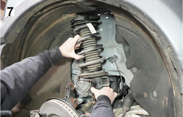
11. [Illustration 7] Carefully lower the control arm enough to remove the strut from the vehicle.
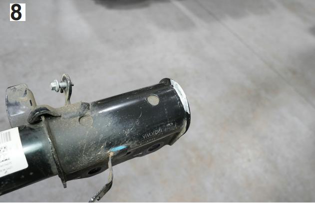
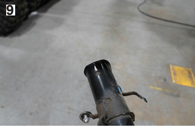
12. [Illustration 8 & 9] Using the appropriate sanding tool, grind the lower strut edge down; paint the ground edge.
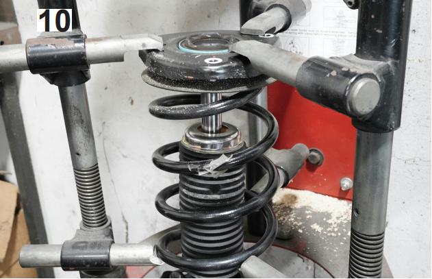
13. [Illustration 10] Place the strut assembly in a compressor, once compressed carefully remove the strut top plate.
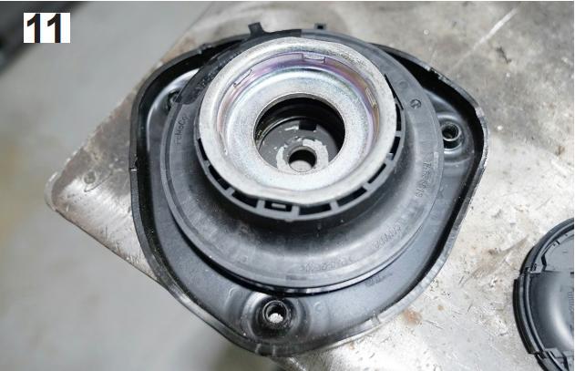
14. [Illustration 11] Place the bump stop cup, bump stop and boot into the new preload spacer.
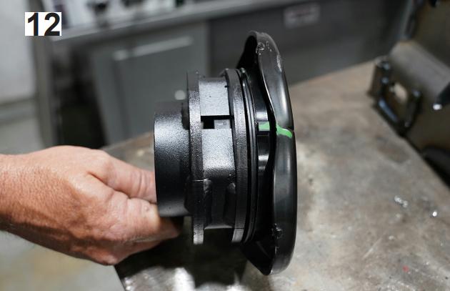
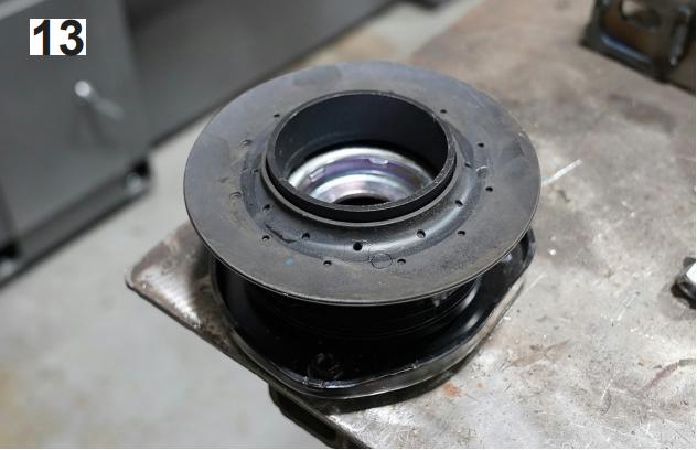
15. [Illustration 12 & 13] Remove the coil spring isolator from the top plate and install the new preload spacer (55-01-9755) onto the top plate,
then place the coil spring isolator onto the new preload spacer.
16. Reinstall the top plate assembly onto the strut.
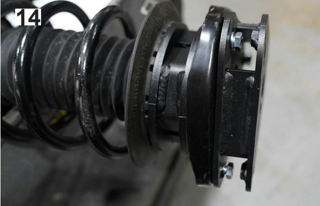
17. [Illustration 14] Place the new strut spacer (55-02-9755) on the top of the strut and secure using the 8mm hardware.
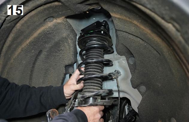
18. [Illustration 15] Install the strut back into the vehicle.
19. Raise the control arm up to seat the upper strut mount in position and secure the upper mount using the factory hardware.
20. Reinstall the strut cover using the factory hardware.
21. Reclip the windshield wiper cover.
22. Secure the lower mount using the factory hardware. [21mm]
23. Reattach the brake hose to the bracket using the factory hardware. [8mm]
24. [Illustration 16] Install the new sway bar bracket (55-03-9750) and secure the bracket to the stock location using the supplied 12mm hardware placing the bolt from the inside facing out. [19mm]
![Install the new sway bar bracket (55-03-9750) and secure the bracket to the stock location using the supplied 12mm hardware placing the bolt from the inside facing out. [19mm]](https://www.blueovaltrucks.com/wp-content/uploads/2026/01/superlift_ford_maverick_lift_kit_2000.jpg)
25. [Illustration 17] Attach the new sway bar links (MS90841) to the new bracket and the factory sway bar body using the supplied hardware. [19mm]
![Attach the new sway bar links (MS90841) to the new bracket and the factory sway bar body using the supplied hardware. [19mm]](https://www.blueovaltrucks.com/wp-content/uploads/2026/01/superlift_ford_maverick_lift_kit_2100.jpg)
26. Reattach the tie rod end to the knuckle. [15mm]
27. Reinstall the tires and wheels. Tighten the lug nuts.
28. When the tires / wheels are installed, always check for and remove any corrosion, dirt, or foreign material on the wheel mounting surface, or anything that contacts the wheel mounting surface (hub, rotor, etc.). Installing wheels without the proper metal-to-metal contact at the wheel mounting surfaces can cause the lug nuts to loosen and the wheel to come off while the vehicle is in motion.
29. Retighten lug nuts at 500 miles after any wheel change, or anytime the lug nuts are loosened. Failure to do so could cause wheels to come off while vehicle is in motion.
30. With the vehicle still on jack stands, and the suspension “hanging” at full extension travel, check all components for proper operation and clearances. Pay special attention to clearance between the tires / wheels and brake hoses, driveshaft, etc.
31. Lower vehicle to the floor.
REAR INSTALLATION
1. Secure the vehicle on jack stands with a jack under the lower control arm.
2. Remove rear tires.
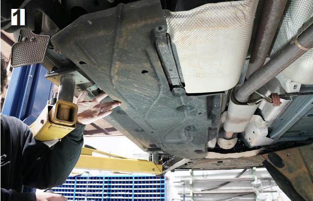
3. [Illustration 1] Remove the bolts holding the sound dampening liner in place.
4. [Illustration 2] Disconnect the lower mount of the sway bar link. [18mm]
![Disconnect the lower mount of the sway bar link. [18mm]](https://www.blueovaltrucks.com/wp-content/uploads/2026/01/superlift_ford_maverick_lift_kit_2300.jpg)
5. [Illustration 3] Remove the lower shock bolt. [15mm]
![Remove the lower shock bolt. [15mm]](https://www.blueovaltrucks.com/wp-content/uploads/2026/01/superlift_ford_maverick_lift_kit_2400.jpg)
6. Loosen but do not remove the upper control arm bolt at the knuckle. [15mm]
7. [Illustration 4] Remove the lower bolt control arm bolt at the knuckle. [15mm]
![Remove the lower bolt control arm bolt at the knuckle. [15mm]](https://www.blueovaltrucks.com/wp-content/uploads/2026/01/superlift_ford_maverick_lift_kit_2500.jpg)
8. [Illustration 4] Lower the lower control arm enough to remove the coil spring from the vehicle.
9. [Illustration 5] Remove the link arm bolts from the frame, place a new spacer (05-9755) between the link arm and the frame and secure the link arm and spacers using the supplied 14mm hardware. [21mm]
![Remove the link arm bolts from the frame, place a new spacer (05-9755) between the link arm and the frame and secure the link arm and spacers using the supplied 14mm hardware. [21mm]](https://www.blueovaltrucks.com/wp-content/uploads/2026/01/superlift_ford_maverick_lift_kit_2600.jpg)
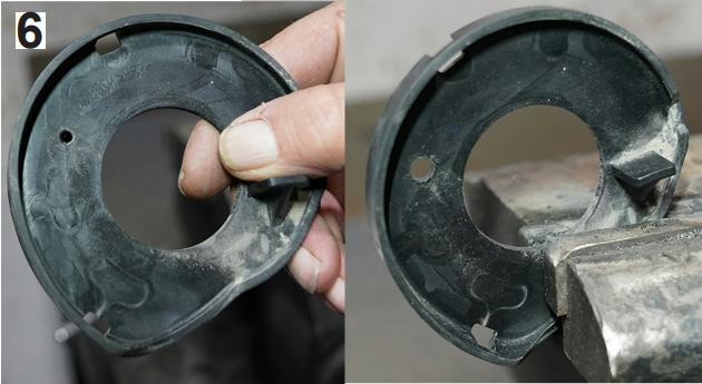
10. [Illustration 6] Remove the coil spring isolator from the lower control arm and drill the hole out to 6mm or 0.25”.
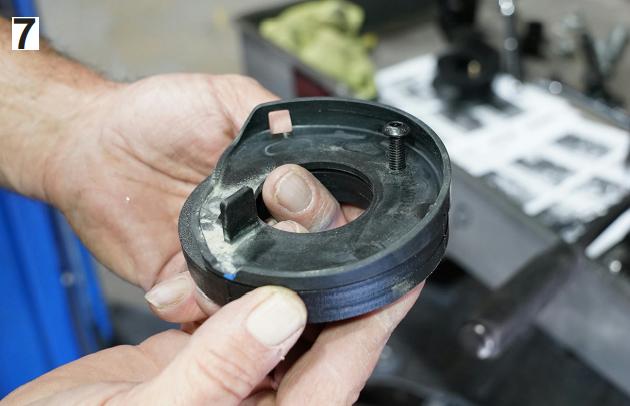
11. [Illustration 7] Install the supplied 6mm bolt through the coil spring isolator and place two new 0.25” thick coil spring spacers (55-04-9755) onto the bolt then place the isolator and spacers in the factory location with the bolt acting as a locating pin.
12. Mark the orientation of the upper coil spring isolator and remove.
13. [Illustration 8] Place one new 0.179” coil spring spacer (55-03-9755) over the upper frame mount then reinstall the coil spring isolator to hold the spacer in place.
14. Reinstall the coil spring and raise the lower control arm to hold the coil in place.
15. Reinstall the lower control arm bolt.
16. Reinstall the lower shock bolt.
17. Reattach the sway bar link.
18. Tighten the upper control arm bolt.
19. Reinstall the tires and wheels. Tighten the lug nuts.
20. When the tires / wheels are installed, always check for and remove any corrosion, dirt, or foreign material on the wheel mounting surface, or anything that contacts the wheel mounting surface (hub, rotor, etc.). Installing wheels without the proper metal-to-metal contact at the wheel mounting surfaces can cause the lug nuts to loosen and the wheel to come off while the vehicle is in motion.
21. Retighten lug nuts at 500 miles after any wheel change, or anytime the lug nuts are loosened. Failure to do so could cause wheels to come off while vehicle is in motion.
FINAL CHECKS
1. Check all hardware for proper torque specifications.
2. With the vehicle on the ground, check all components for proper operation and clearances. Pay special attention to the clearance between the tires / wheels, brake hoses, wiring, etc. Check tire/wheel clearance with the fenders/bumper as well as with the steering knuckle.
3. Realign vehicle to factory OEM specifications. It is necessary to have a proper and professional wheel alignment performed by a certified alignment technician. Align the vehicle to factory specifications. It is recommended that your vehicle alignment be checked after any off-road driving.
4. Re-adjust headlights to proper setting. In addition to your vehicle alignment, for your safety and others, it is necessary to check and adjust your vehicle head lamps for proper aim and alignment.
5. Activate four wheel drive system and check for proper engagement.
6. Install the Warning to Driver decal on the inside of the windshield or dash within the driver’s view.
IMPORTANT MAINTENANCE INFORMATION
It is the ultimate buyer’s responsibility to have all bolts / nuts checked for tightness after the first 100 miles and then every 1000 miles. The steering, suspension and driveline systems, plus wheel alignment should be inspected by a qualified professional mechanic at least every 3000 miles.
LIMITED LIFETIME WARRANTY / WARNINGS
Your SUPERLIFT® product is covered by the Limited Warranty explained below that gives you specific legal rights. This limited warranty is the only warranty SUPERLIFT® makes in connection with your product purchase. SUPERLIFT® neither assumes nor authorizes any retailer or other person or entity to assume for it any other obligation or liability in connection with this product or limited warranty.
SUPERLIFT, LLC, LIMITED LIFETIME WARRANTY
What is covered? Subject to the terms below, SUPERLIFT® will repair or replace its products found defective in materials or workmanship for so long as the original purchaser owns the vehicle on which the product was originally installed. Your warrantor is SUPERLIFT, LLC, doing business as SUPERLIFT® Suspension Systems (“SUPERLIFT®”).
What is not covered? Your SUPERLIFT® Limited Warranty does not cover products SUPERLIFT® determines to have been damaged by or subjected to:
• Alteration, modification or failure to maintain.
• Normal wear and tear (bushings, rod ends, etc.). Scratches or defects in product finishes (powder coating, plating, etc.).
• Damage to, or resulting from, the vehicle’s electronic stability system, related components or other vehicle systems.
• Racing or other vehicle competitions or contests. Accidents, impact by rocks, trees, obstacles or other aspects of the environment.
• Theft, vandalism or other intentional damage. Remedy Limited to Repair or Replacement. The exclusive remedy provided hereunder shall, upon SUPERLIFT’s inspection and at SUPERLIFT’s option, be either repair or replacement of the product covered under this Limited Warranty. Customers requesting warranty consideration should contact SUPERLIFT® by phone (1-800-551-4955) to obtain a Returned Goods Authorization number. All removal, shipping and
installation costs are customer’s responsibility.
If a replacement part is needed before the SUPERLIFT® part in question can be returned, you must first purchase the replacement part. Then, if the part in question is deemed warrant-able, you will be credited / refunded.
OTHER LIMITATIONS – EXCLUSION OF DAMAGES – YOUR RIGHTS UNDER STATE LAW
• Neither SUPERLIFT® nor your independent SUPERLIFT® dealer are responsible for any time loss, rental costs, or for any incidental, consequential or other damages you may have.
• This Limited Warranty gives you specific rights, and this is the only warranty SUPERLIFT® makes in connection with your product purchase. You may also have other rights that vary from state to state.
For example, while all implied warranties are disclaimed herein, any implied warranty required by law is limited to the terms of our Limited Lifetime Warranty as described above. Some states do not allow limitations of how long an implied warranty lasts and / or do not allow the exclusion or limitation of incidental or consequential damages, so the limitations and exclusions herein may not apply to you. SUPERLIFT® neither assumes nor authorizes any retailer or other person or entity to assume for it any other obligation or liability in connection with this product or Limited Warranty.
IMPORTANT PRODUCT USE AND SAFETY INFORMATION / WARNINGS
As a general rule, the taller a vehicle is, the easier it will roll over. Offset, as much as possible, what is lost in rollover resistance by increasing tire track width. In other words, go “wide” as you go “tall”; always use as wide a tire and wheel combination as feasible to enhance vehicle stability. We strongly recommend,
because of rollover possibility, that the vehicle be equipped with a functional roll bar and cage system. Seat belts and shoulder harnesses should be worn at all times. Avoid situations where a side rollover may occur. Generally, braking performance and capabilities are decreased when significantly larger / heavier tires and wheels are used. Take this into consideration while driving. Also, changing axle gear ratios or using tires that are taller or shorter than factory height will cause an erroneous speedometer reading. On vehicles equipped with an electronic speedometer, the speed signal impacts other important functions as well. Speedometer recalibration for both mechanical and electronic types is highly recommended.
Do not add, alter, or fabricate any factory or aftermarket parts to increase vehicle height over the intended height of the SUPERLIFT® product purchased. Mixing component brands is not recommended.
About The Author
Growing up, my father always believed that every family needed a truck—there’s just something about having a vehicle capable of hauling anything at a moment’s notice. That philosophy stuck with me, and it’s been the foundation of my lifelong passion for Ford trucks.
While I’m best known for my work with Ford Rangers, I’ve owned a wide variety of Ford trucks over the years—including F-150s, F-250s, F-350s, and even larger rigs like the Ford Excursion, Ford Expedition, and a 1982 Ford Econoline Sportsmobile camper van. I’ve used these vehicles for everything from family transportation to towing car trailers and campers, and each one has fueled my love for Ford’s versatility and durability.
I especially enjoy the styling of 1970s and 1980s Ford trucks—the bold designs, rugged presence, and classic charm are timeless. Sharing my passion for Ford trucks, vans, and SUVs with other enthusiasts online brings me a great deal of joy, and it’s why I created Blue Oval Trucks.
This website is dedicated to helping Ford truck enthusiasts explore, learn about, and celebrate these incredible vehicles. While I share my expertise and experiences here, Blue Oval Trucks is an independent enthusiast site and is not affiliated with Ford Motor Company.