
2005-2007 Ford Super Duty Upfitter Switches:
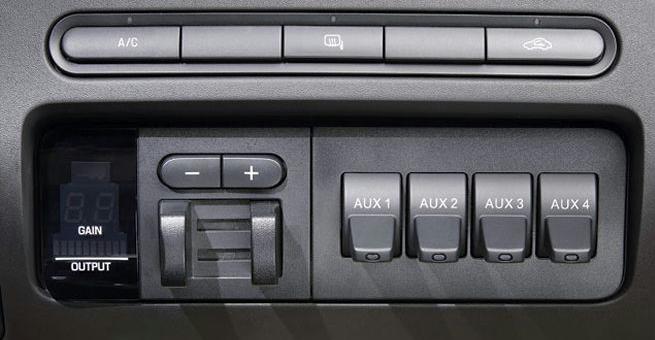
The Ford Upfitter Switches are optional instrument panel mount switches (Option Code 66S) (see Photo 1) that control passenger side mounted relays. These relays power four blunt cut wires that can be found beneath the steering column and behind the passenger compartment fuse panel also called the Central Junction Box (CJB). The wires are part of the harness connected to the “K” connector (C270K) on the back of the CJB (see Attachment II & III). The four wires are as follows (see Photo 3):
| Switches | Circuit | Color | Fuse |
| Aux 1 | 1936 | Orange/Light Green | 30 Amp |
| Aux 2 | 1933 | Orange | 30 Amp |
| Aux 3 | 1934 | Orange/Yellow | 10 Amp |
| Aux 4 | 1935 | Orange/Light Blue | 10 Amp |
To find the wires:
1. Remove the fuse panel trim cover below the steering column.
2. Remove the four fasteners holding the CJB.
3. Lower the CJB without disconnecting any connectors.
4. Locate connector “K” (see Attachment II & III) on the back of the CJB and the harness connected to it.
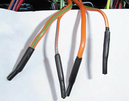
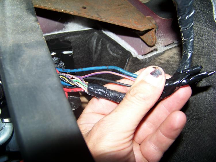
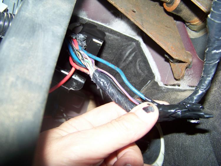
5. Locate the four blunt cut wires with shrink wrap on the harness connected to the “K” connector (See Photo
Operating Procedure:
The Upfitter Switches are operational when the ignition key is in the run position (see Attachment I). The Upfitter Switches cannot be utilized in any other operational mode. The power to the switches is relay controlled and was designed to operate in the “run” mode to reduce the possibility of draining the battery(ies).
2008 Ford Super Duty Upfitter Switches:
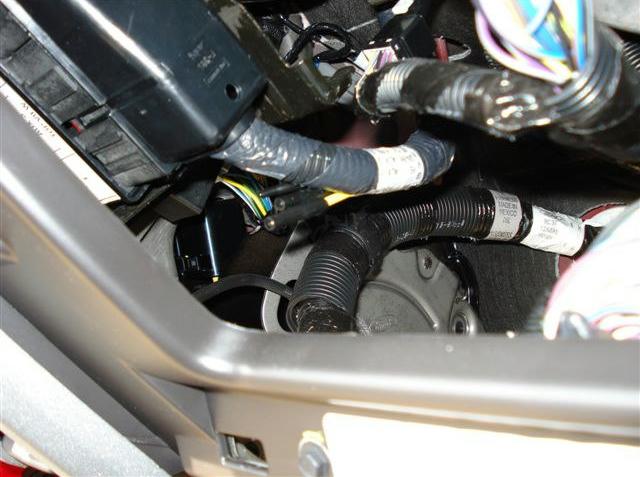
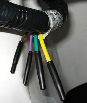
The Ford Upfitter Switches are optional instrument panel mount switches (Option Code 66S) that control passenger side mounted relays. These relays power four blunt cut wires that are taped on a harness near the relay pack that can be found beneath the instrument panel and to the left of the steering column. The four blunt cut wires are as follows:
| Switches | Circuit | Color | Fuse |
| Aux 1 | CAC05 | Yellow | 30 Amp |
| Aux 2 | CAC06 | Green/Brown | 30 Amp |
| Aux 3 | CAC07 | Violet/Green | 10 Amp |
| Aux 4 | CAC08 | Brown | 15 Amp |
To find the wires:
1. Remove the trim cover below the steering column.
2. Locate the relay pack beneath the instrument panel and to the left of the steering column.
3. Locate the four blunt cut wires with shrink wrap on the harness near the relay pack.
Operating Procedure:
The Upfitter Switches are operational when the ignition key is in the “RUN” position only. The power to the switches is relay controlled and was designed to operate in the “RUN” mode to reduce the possibility of draining the battery(ies).
2010 Ford Super Duty Upfitter Switches:
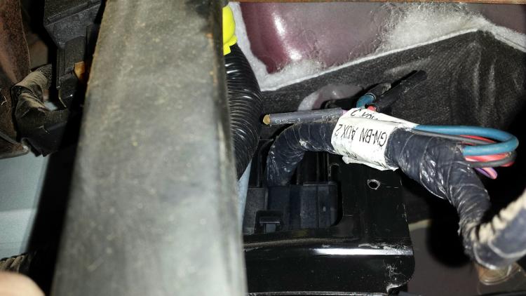
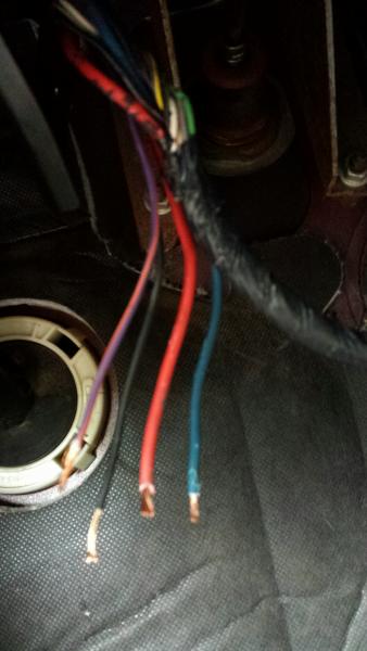
Trying to find the wires for the upfitter switches on your 2010 Super Duty? Can’t find the wires that match the colors listed in your owners manual? Ya, Ford apparently has a sense of humor. Even stranger, the wires were wrapped with a label that listed the wire colors that are in the book, but the wires didn’t match the label. Got to love it.
After getting out my multi-meter, I switched on each upfitter switch one by one and tested the wires for 12-volts. Sure enough, these were them.
Auxiliary 1= Red wire
Auxiliary 2 = Blue wire
Auxiliary 3 = Purple / Orange Wire
Auxiliary 4 = Black wire

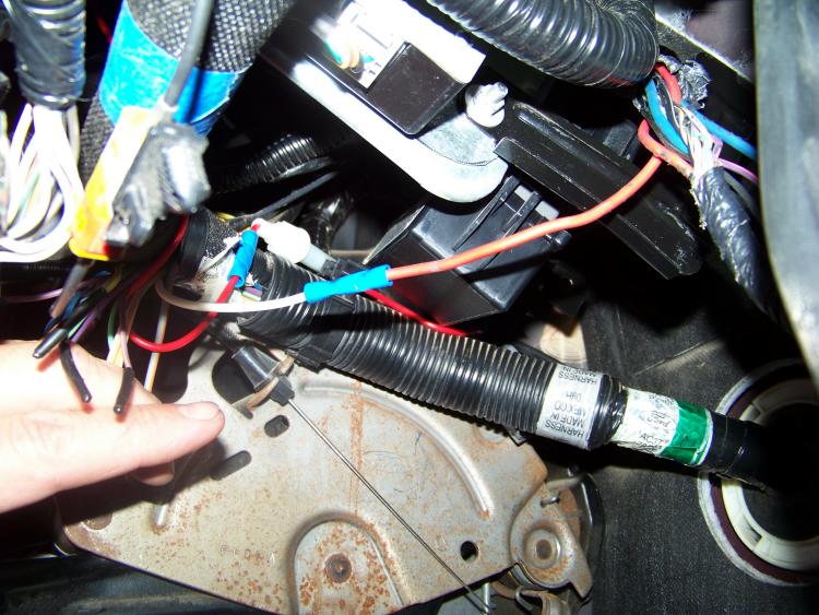
Above you can see where I took the red wire (looks orange) and connected it to the white wire that Ford provided to go through the fire wall. The wire comes out at the top of the firewall in the engine compartment on the drivers side. From there I attached the wiring for some marker lights on my running boards.
2011 And Later F-Series Super Duty Upfitter Switches:
The Ford Upfitter Switches are optional instrument panel mount switches (Option Code 66S) that control passenger side mounted relays. These relays power four blunt cut wires that are taped on a harness near the relay pack that can be found beneath the instrument panel and to the left of the steering column. The four blunt cut wires are as follows:
| Switches | Circuit | Color | Fuse # | Rating |
| Aux 1 | CAC05 | Yellow | F94 | 25A |
| Aux 2 | CAC06 | Green/Brown | F95 | 25A |
| Aux 3 | CAC07 | Violet/Green | F9 | 10A |
| Aux 4 | CAC08 | Brown | F2 | 15A |
To find the wires:
1. Remove the trim cover below the steering column.
2. Locate the relay pack beneath the instrument panel and to the left of the steering column.
3. Locate the four blunt cut wires with shrink wrap on the harness near the relay pack.
Operating Procedure
The Upfitter Switches are operational when the ignition key is in the RUN or ACCY positions. The power to the switches is relay controlled and was designed to operate in the RUN or ACCY mode to reduce the possibility of draining the battery/batteries.
Links:
2005-2008 Ford Upfitter Switches – SVE Bulletin
2008-2010 Ford Upfitter Switches – SVE Bulletin
2011 And Later Ford Upfitter Switches – SVE Bulletin
2005-2011 Ford Upfitter Switches – SVE Bulletin
About The Author
Growing up, my father always believed that every family needed a truck—there’s just something about having a vehicle capable of hauling anything at a moment’s notice. That philosophy stuck with me, and it’s been the foundation of my lifelong passion for Ford trucks.
While I’m best known for my work with Ford Rangers, I’ve owned a wide variety of Ford trucks over the years—including F-150s, F-250s, F-350s, and even larger rigs like the Ford Excursion, Ford Expedition, and a 1982 Ford Econoline Sportsmobile camper van. I’ve used these vehicles for everything from family transportation to towing car trailers and campers, and each one has fueled my love for Ford’s versatility and durability.
I especially enjoy the styling of 1970s and 1980s Ford trucks—the bold designs, rugged presence, and classic charm are timeless. Sharing my passion for Ford trucks, vans, and SUVs with other enthusiasts online brings me a great deal of joy, and it’s why I created Blue Oval Trucks.
This website is dedicated to helping Ford truck enthusiasts explore, learn about, and celebrate these incredible vehicles. While I share my expertise and experiences here, Blue Oval Trucks is an independent enthusiast site and is not affiliated with Ford Motor Company.