
Since 2005, Ford has offered ‘Upfitter Switches’ in their Super Duty trucks. It consists of a switch panel that has wires that terminate under the dash, and a pass through harness in the firewall. The idea is for you to be able to add accessories to either the inside or outside of the truck. I believe that this stemmed for the need to add such things as warning lights or other auxiliary lighting to work vehicles. When the 2010 Ford Raptor came out, it featured the upfitter switches as well. For some strange reason, Ford never offered it on the F-150. Not even with the FX4 off-road package.
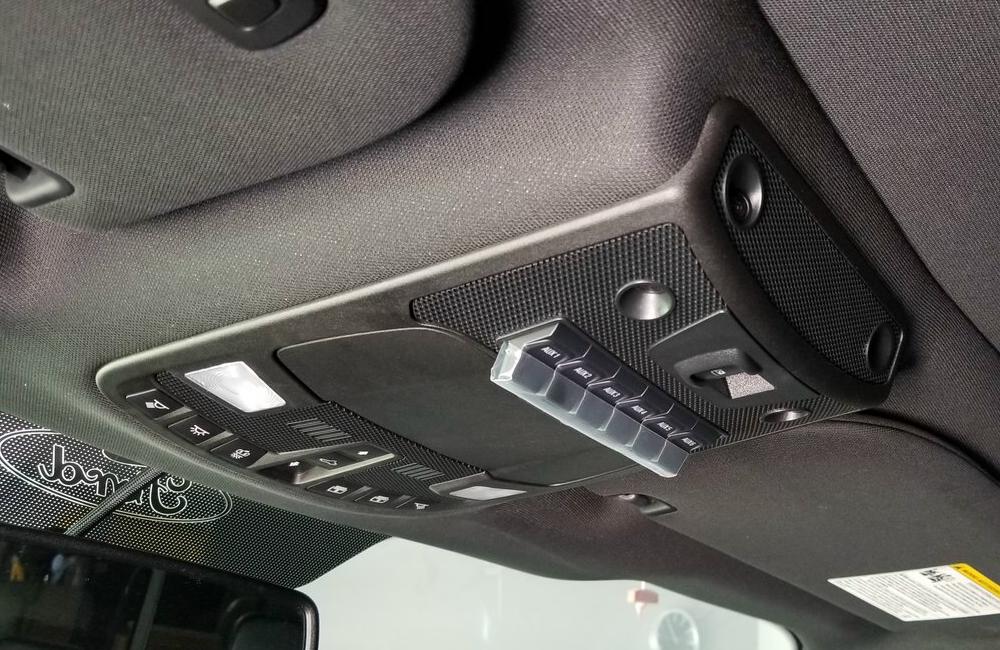
This didn’t stop Ford F-150 owners though. Some have found ways to add the upfitter switches to their trucks. Here’s how you can add the overhead console switches to your 2015 and newer Ford F-150.
Parts Needed:
(1) Overhead Console With Upfitter Switches.
You will need a console that matches your interior as well as the features that your truck has. Check out our page ‘2017+ Ford Overhead Console W/Switches Part Numbers‘ to find the part number for your application.
(1) Wire Assembly / Upfitter Relay Box P/N HC3Z-14A303-F
(1) MEGA/AMG Fuse Block (CLICK HERE)
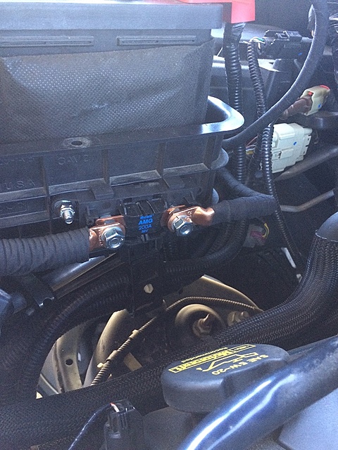
(1) 200 AMP Mega Fuse (CLICK HERE)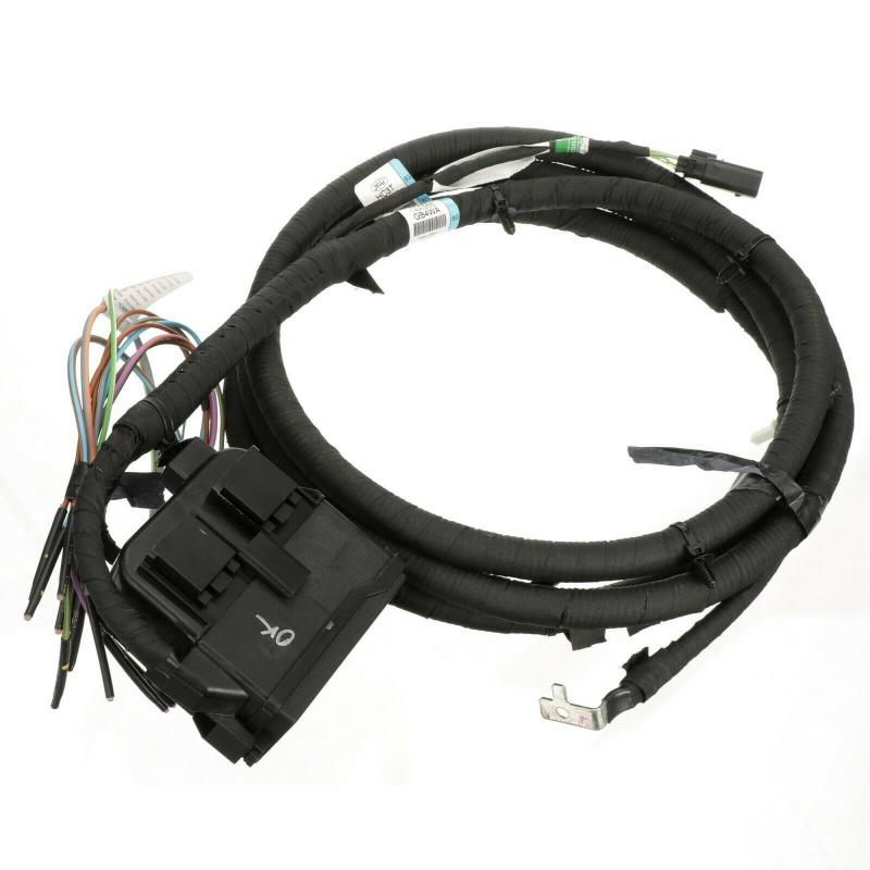
Wire Assembly / Upfitter Relay Box P/N HC3Z-14A303-F
Wire Assembly / Upfitter Relay Box P/N HC3Z-14A303-F
Harness From Switches To Relay Box:
You’ll Need to either make your own harness to connect the relay box to the upfitter switches, or you can buy a new custom harness:
New Harness:
(1) Boosted Grey Goose Designs Raptor/SD Upfitter Harness 2015-2020 F150 – CLICK HERE
Make Your Own Harness:
(1) Wire Assembly That Plugs Into The Upfitter Switches P/N HC3Z-15A404-B
(1) Ford Wire Assembly P/N AU2Z-14S411-AMB (Replaces 4W1Z-14489-BA, AU2Z-14S411-AMA, WPT-1125)
(11) 10-Foot Rolls of 20-Gauge Automotive Wire In 11-Different Colors
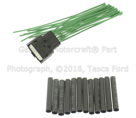
P/N AU2Z-14S411-AMB (Replaces 4W1Z-14489-BA, AU2Z-14S411-AMA, WPT-1125)
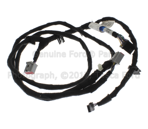
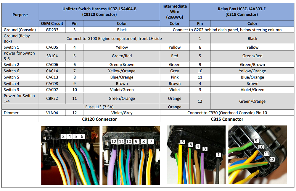
Upfitter Switch Harness P/N HC3Z-15A404-B
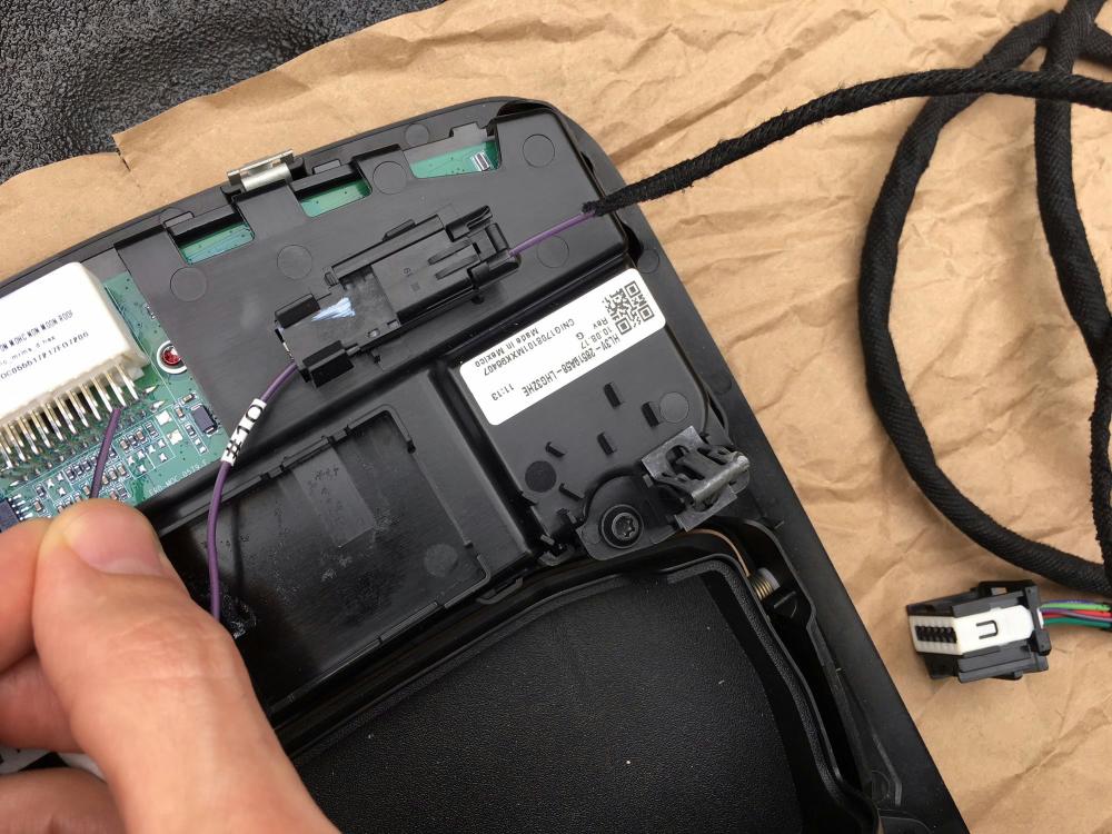
Illumination of Switches:
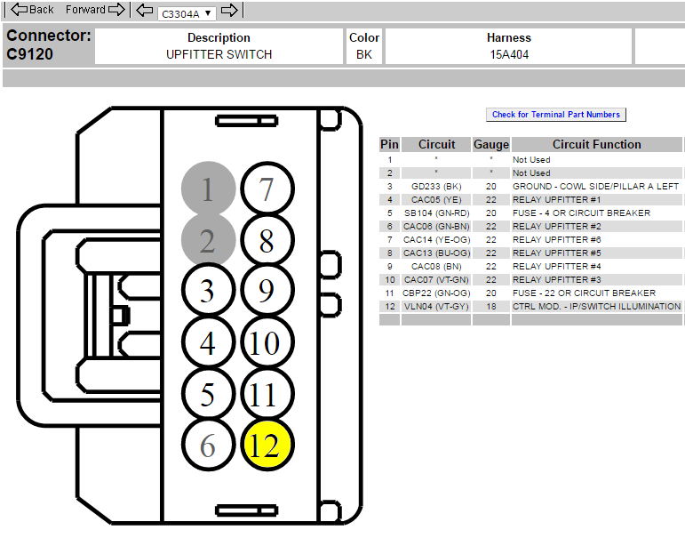
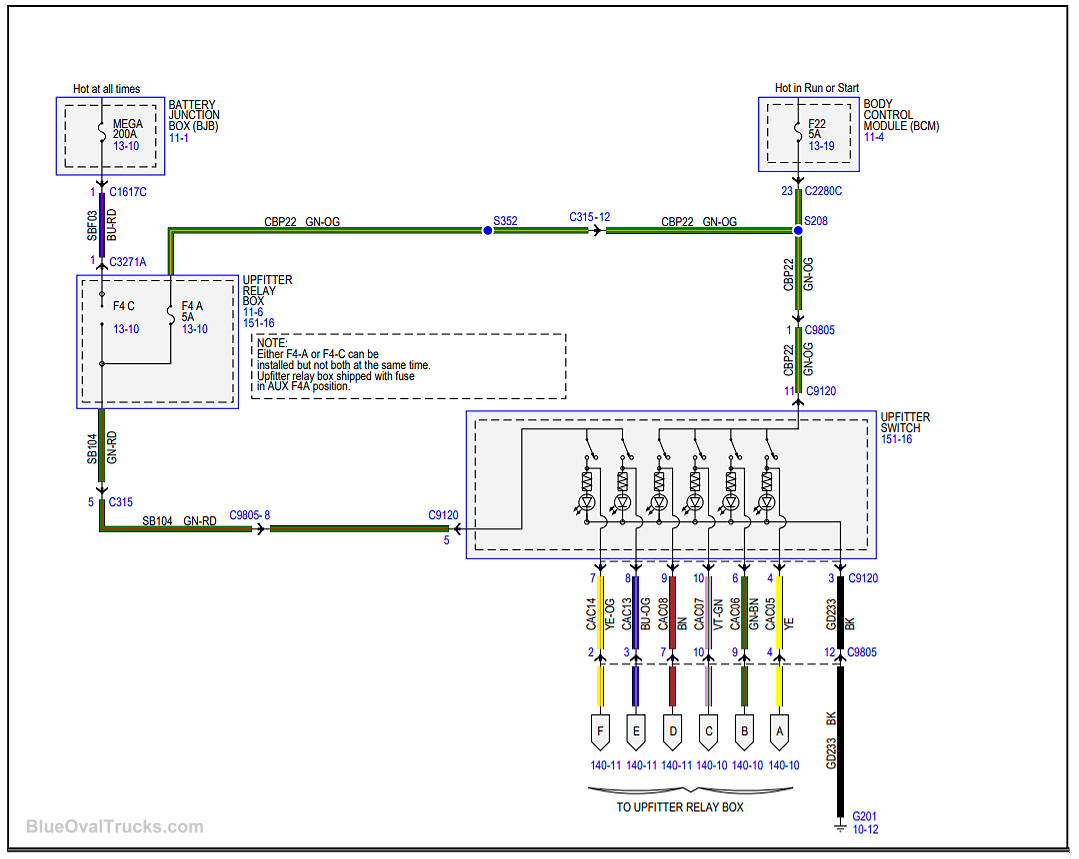
C9120 pin out clearly shows VLN04 (#12) as the illumination circuit.
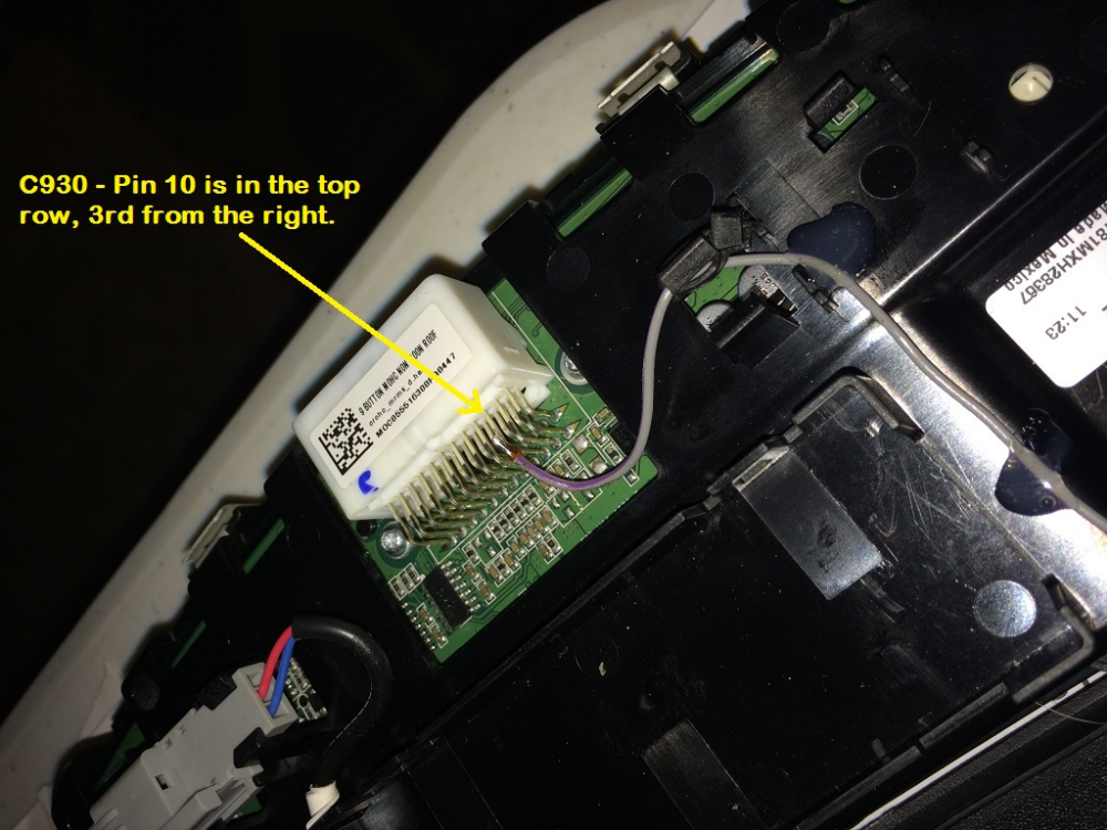
VLN04 is already available on the main overhead console 20 pin connector C930/ Pin 10 / VT-GY wire.
If you want factory function of the upfitter switch illumination, this is the circuit to tap into for illumination. The BCM already controls this circuit for all the intended illumination on/off situations.
Granted it is a bit difficult to tap that wire, not a lot of slack, but patience and it will work out.
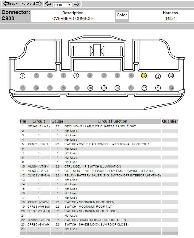
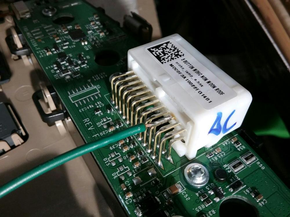
(Connecting to Pin 10 for illumination to the upfitter switches)
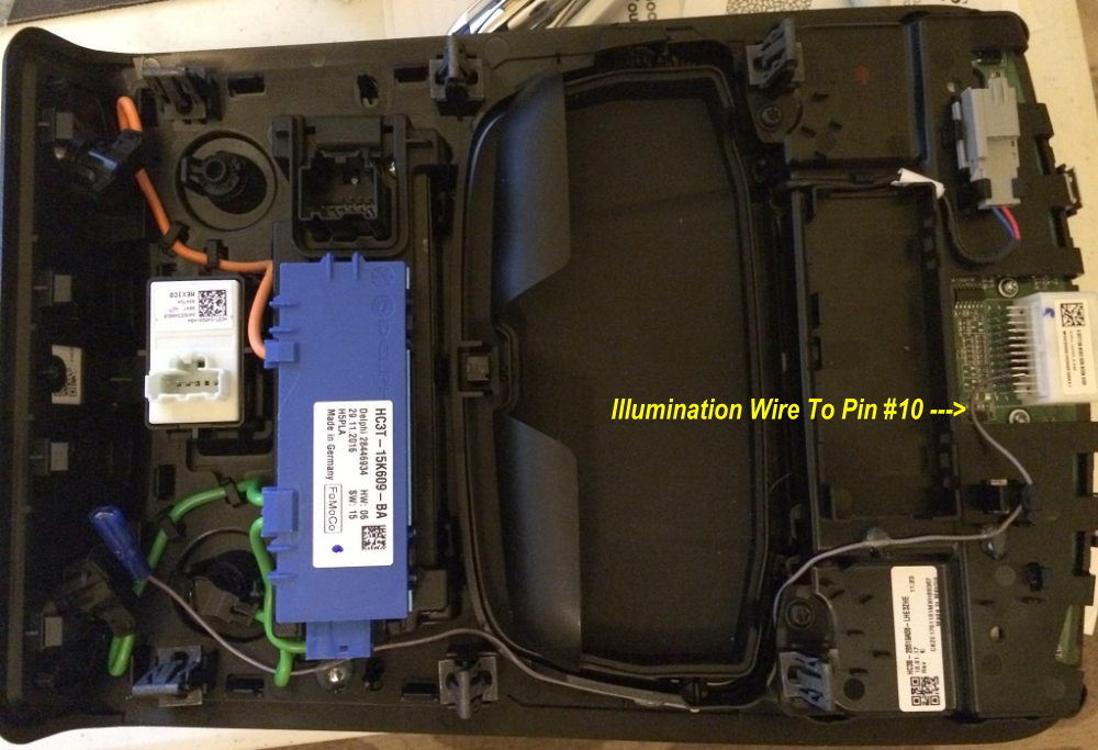
Boosted Grey Goose Designs Harness – Illumination:
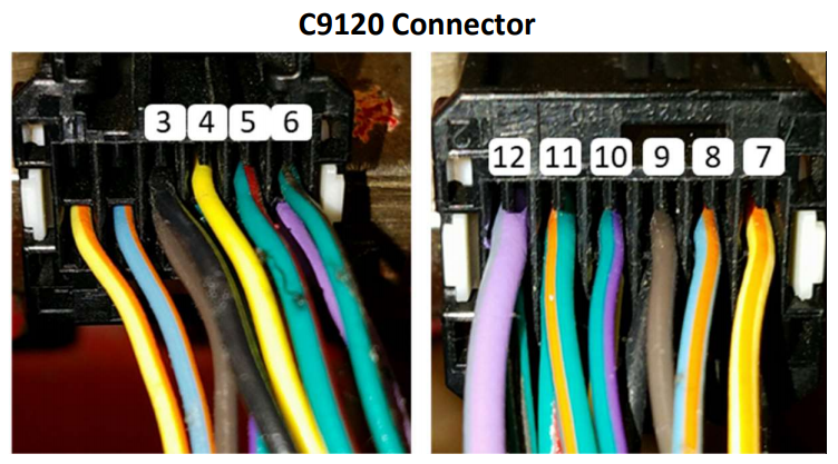
If using the Boosted Grey Goose Designs harness, you’ll need to solder the purple wire to the 10th pin from the left. This is the same circuit described above. The wire is marked so you know where you need to connect for +12 power for the lights in the switches. By soldering here, the lights in the switches will dim with the rest of the lights in the console just like factory.
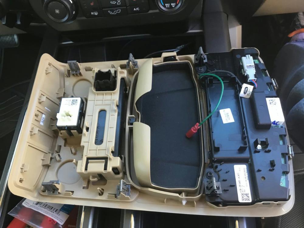
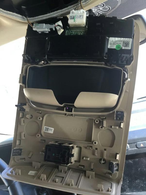
Overhead Console Installation:
1) Remove the existing console using a plastic trim removal tool. Disconnect the existing connectors: SYNC microphone, power
sliding rear window switch, and lighting connectors.
2) Remove the grab handle on the drivers side A-pillar. According to Ford, the bolt covers are disposable. Try carefully to take them off without breaking the locking tabs. If you break one, the part numbers are: FL3Z-1531459-BC and FL3Z-1531459-AC.
3) If you chose to make your own harness, you’ll need to take the upfitter wiring harness PN HC3Z-15A404-B and extend each wire with one of the different color wires that you bought. You will have to make sure that the harness is long enough to reach in to the engine bay and plug in to the relay box. If you bought the Boosted Grey Goose harness, use that.
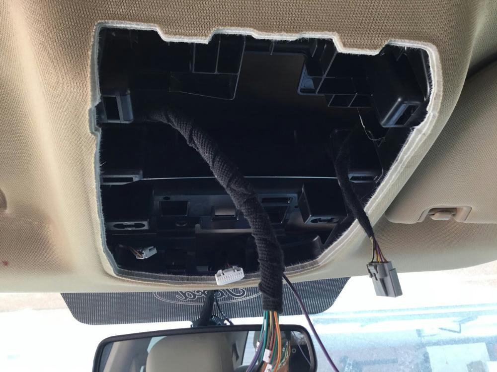
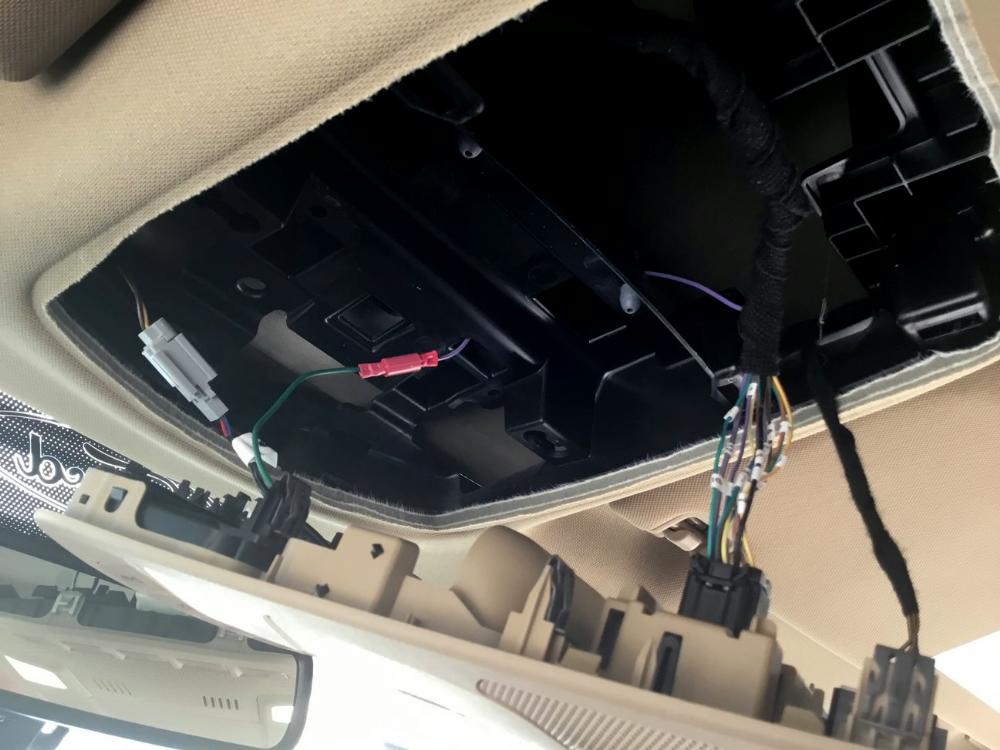
4) With the harness attached to the upfitter switches, pull the wires (harness) from the console across the roof, down the A-pillar and into the driver foot well. Using an electricians fish tape or an other guide wire will help guide and pull the harness through.
5) In the driver’s foot well, connect the black ground wire that comes from C9120 Pin 3 (Black) to the factory ground point G202 behind the dash panel, below the steering column.
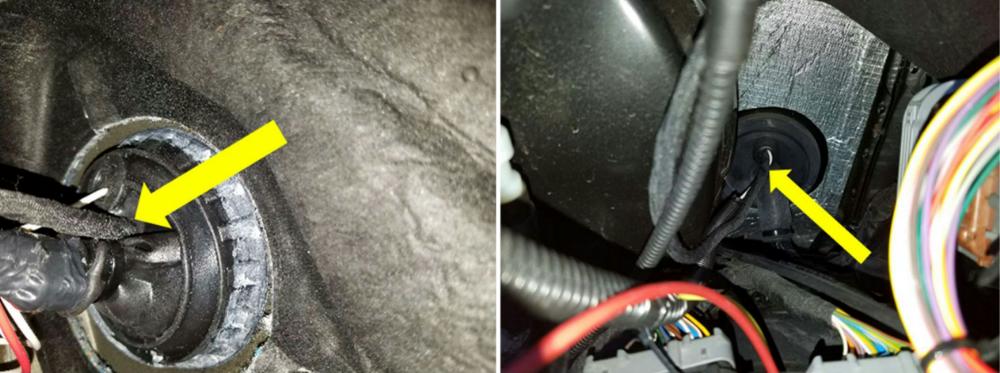
6) With the help of a short piece of stiff wire and some pure silicone spray or liquid soap, push/pull the wire bundle though the rubber gasket in the firewall and into the engine bay.
7) You may want to finish all of the connections and test them before snapping the new console up in to place.
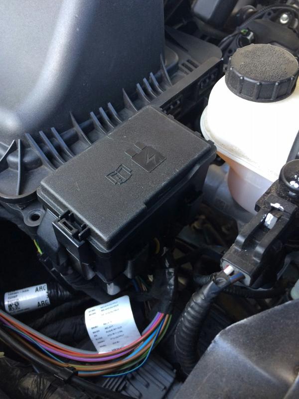
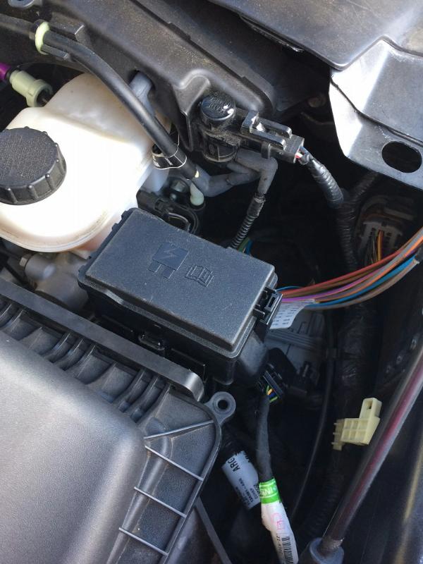
Mounting The Relay Box:
You’ll need to make a bracket to mount the relay box.
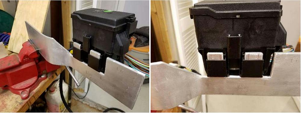
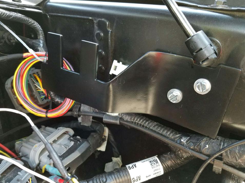
Some have made a mounting bracket out of 3/16” x 3” Aluminum 6061 stock and mounted it to the inner fender with 1/4″ x 20 zinc coated steel screws.
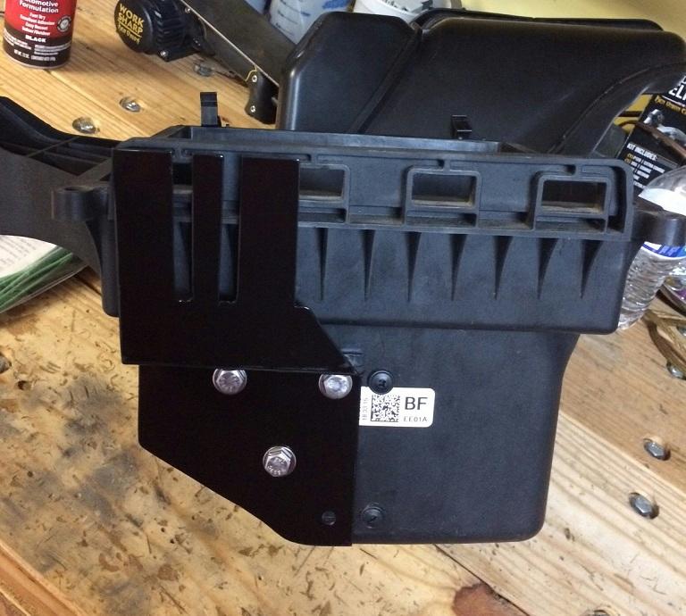
Others have made a bracket out of 16 gauge mild steel and bolted to the air box.
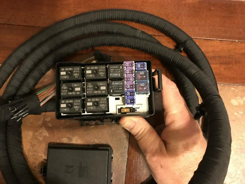
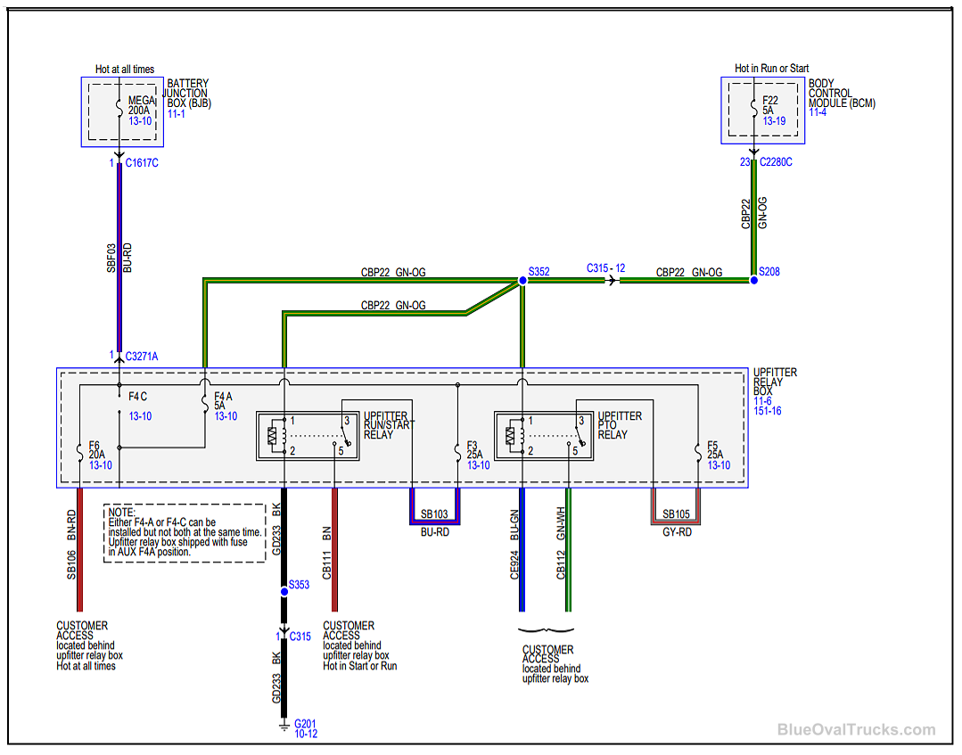
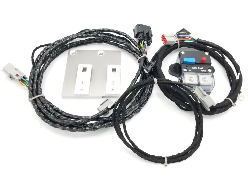
Wiring The Relay Box:
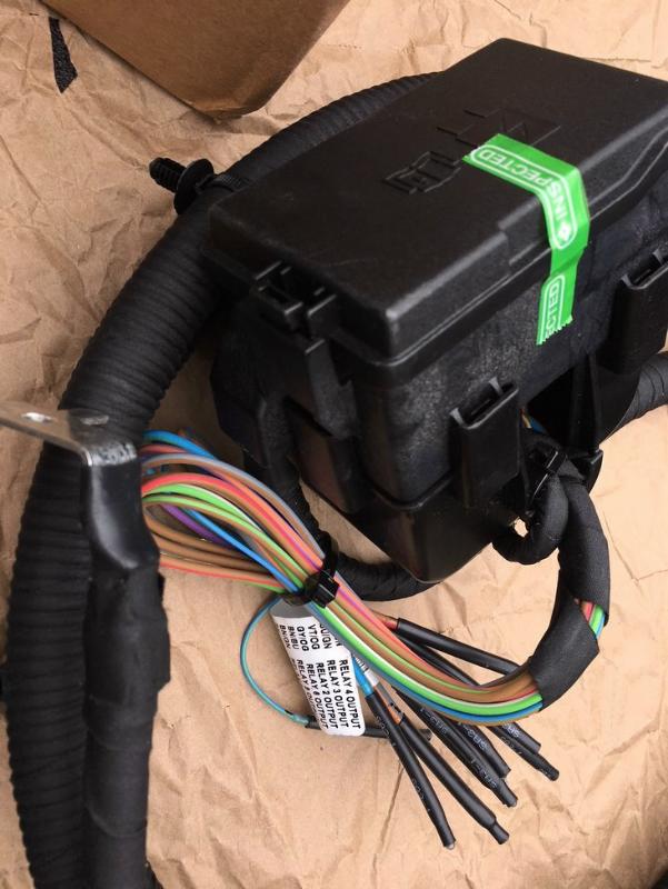
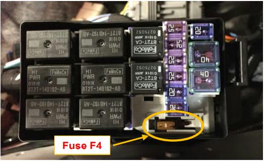
You can see in the photo above that the wiring on the relay box is labelled.
There is (1) big blue wire (#2 gauge) that mounts directly to battery with a 200 amp mega fuse added inline near the battery. This is the constant +12V to run all the relays and feeds switches 5/6 if the 5 amp fuse is moved over.
The black wire to the switches must also be connected to ground. This is the shared ground for relay box and switches.
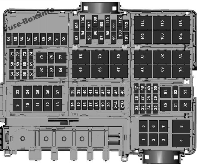
The Green/Orange (hot run/start) wire needs hooked to the 113 fuse in the engine compartment with a Add-a-Fuse and a 5 amp fuse. This is shared run/start for the relay box and also goes to the switches. All the other wires are color to color to run from relay box to the switches.
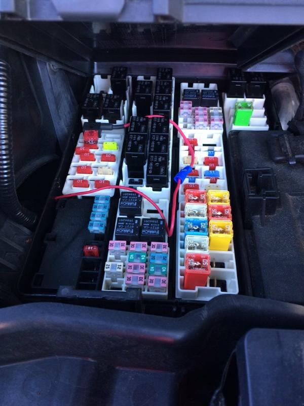
Configuring Upfitter Switches 5 & 6 To Be Hot At All Time:
Upfitter relay box fuse F4 (5A) can be put into one of two positions. In Position A, auxiliary switch 5 and 6, operate with the ignition in RUN or START.
In Position C, auxiliary switch 5 and 6 operate hot at all times.
The following procedure describes how to configure #5 and #6 upfitter switches to Battery hot.
1. Remove upfitter relay box cover.
2. Remove 5 Amp fuse located on the lower right hand corner of the upfitter relay box.
3. Slide the contact guard from position A (left) to position C (right) position.
4. Re-insert 5 Amp fuse into position C (right) position.
5. Replace relay box cover.
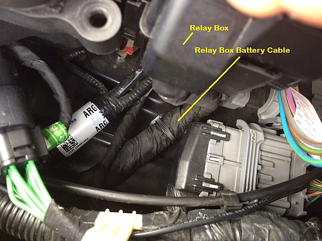
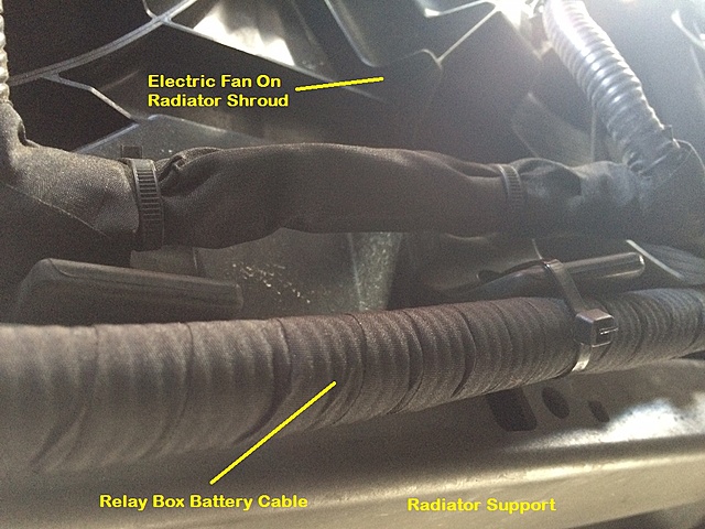
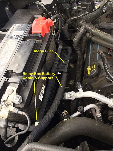
The Battery Cable:
The last part of the install is to route the relay box battery cable and to install the Mega Fuse. This person routed the cable down along the fender, towards the radiator.
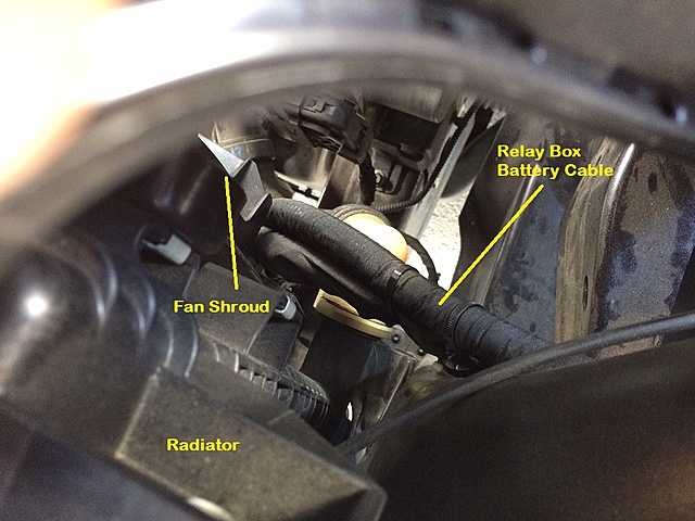
They followed a large cable across the radiator support.
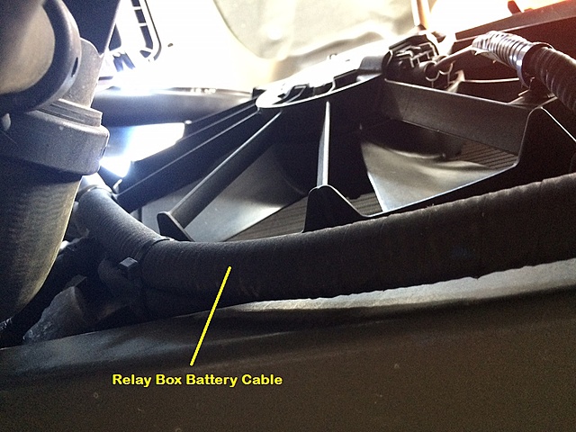
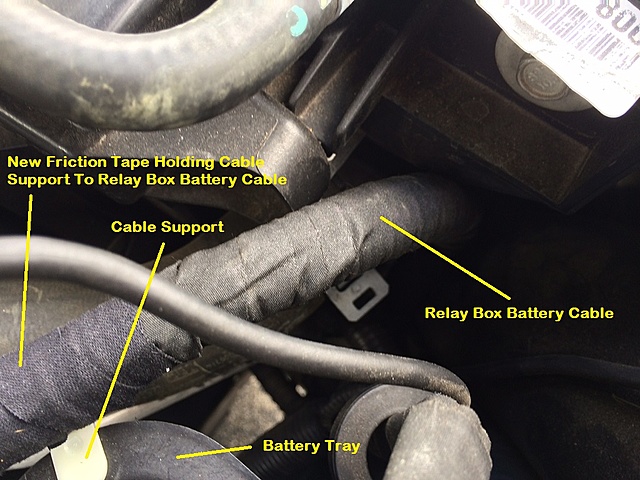
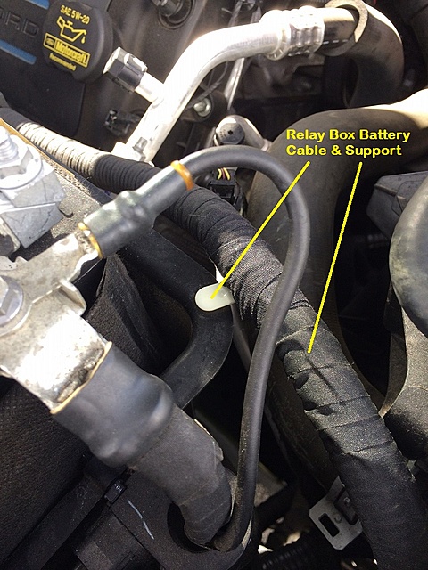
And then brought the cable up, just behind the passenger headlight. They removed a cable support that is on the cable from Ford. Using 3M Friction Tape they secured the support to the cable. They then drilled a hole in the battery tray and pushed the cable support into it, making a nice secure anchor point.
They removed the battery and drilled two holes for the Mega Fuse, and then used stainless bolts with Nyloc nuts to secure it to the battery tray.
They then crimped solid copper 2/0 lugs on the cables and connected them to the Mega Fuse.
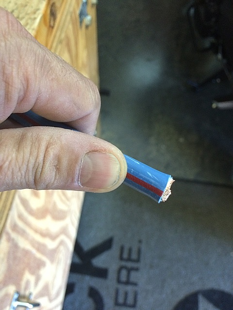
The relay box battery cable is too long for this route. Leaving the factory terminal on the cable, measured the distance from the positive battery terminal to the Mega Fuse terminal and cut it to fit. If you are wondering, there is plastic loom around the 2/0 cable – all wrapped up in friction tape.
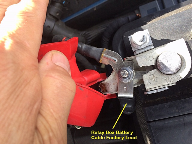
Connected the terminal to the battery post. The terminals are all made of the same metal, which will help eliminate corrosion caused by dissimilar metals.
Connecting The Upfitter Switch Harness To The Relay Box:
1) Verify that the AU2Z-14S411-AMB (WPT-1125) pigtail fits the connector on the relay box.
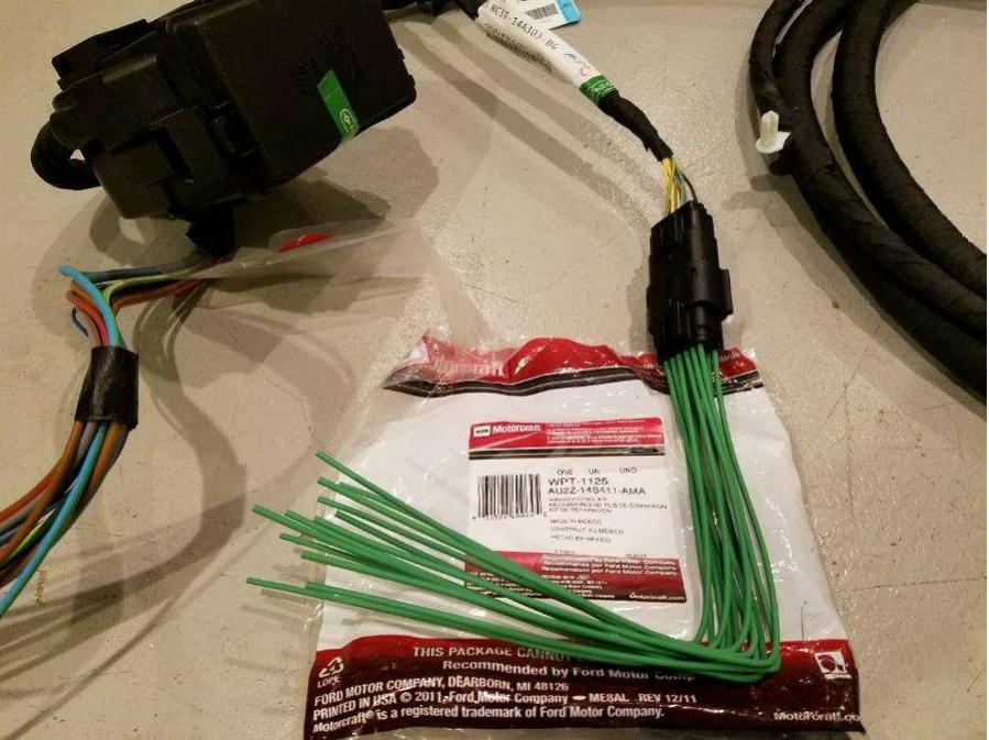
2) Identified and label the wires on the AU2Z-14S411-AMB pigtail for splicing to wire bundle coming from overhead console.
3) Soldered/spliced each of the wires coming from the overhead console to the WPT-1125 pigtail.
Link:
For more information on the 2017+ upfitter switches, see ‘2017 And Never Ford Super Duty AUX Upfitter Switches‘
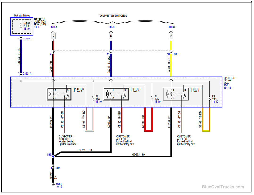
Wiring Schematics
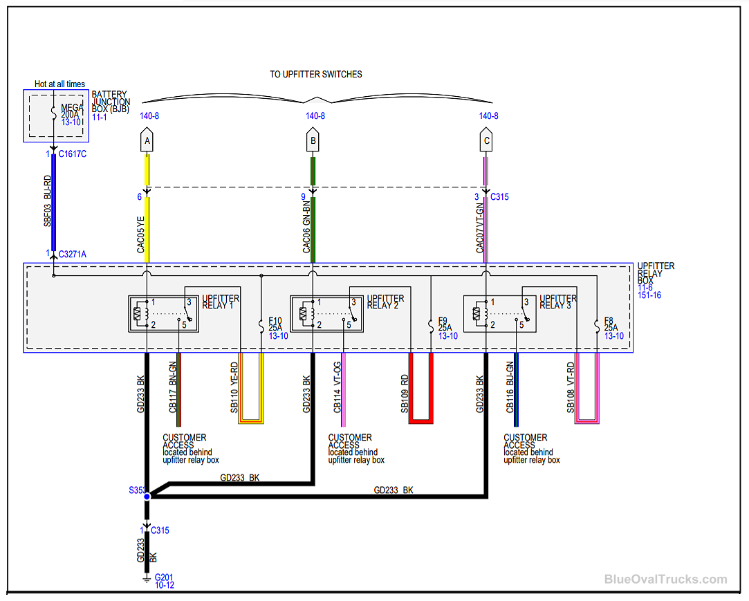
The Boosted Grey Goose Designs Harness Kit:
If you’ve read through this, you know that you have to buy a harness P/N HC3Z-15A404-B, extend it, and then add a plug P/N AU2Z-14S411-AMB (WPT-1125) to connect it to the relay box. You also need to fabricate a bracket to mount the relay box, and add a mega fuse. If you don’t want to do all of that, the Boosted Grey Goose Design kit includes a complete harness to connect the switches to the relay box, a mounting bracket for the relay box, and a circuit breaker. CLICK HERE for more information.
About The Author
Growing up, my father always believed that every family needed a truck—there’s just something about having a vehicle capable of hauling anything at a moment’s notice. That philosophy stuck with me, and it’s been the foundation of my lifelong passion for Ford trucks.
While I’m best known for my work with Ford Rangers, I’ve owned a wide variety of Ford trucks over the years—including F-150s, F-250s, F-350s, and even larger rigs like the Ford Excursion, Ford Expedition, and a 1982 Ford Econoline Sportsmobile camper van. I’ve used these vehicles for everything from family transportation to towing car trailers and campers, and each one has fueled my love for Ford’s versatility and durability.
I especially enjoy the styling of 1970s and 1980s Ford trucks—the bold designs, rugged presence, and classic charm are timeless. Sharing my passion for Ford trucks, vans, and SUVs with other enthusiasts online brings me a great deal of joy, and it’s why I created Blue Oval Trucks.
This website is dedicated to helping Ford truck enthusiasts explore, learn about, and celebrate these incredible vehicles. While I share my expertise and experiences here, Blue Oval Trucks is an independent enthusiast site and is not affiliated with Ford Motor Company.